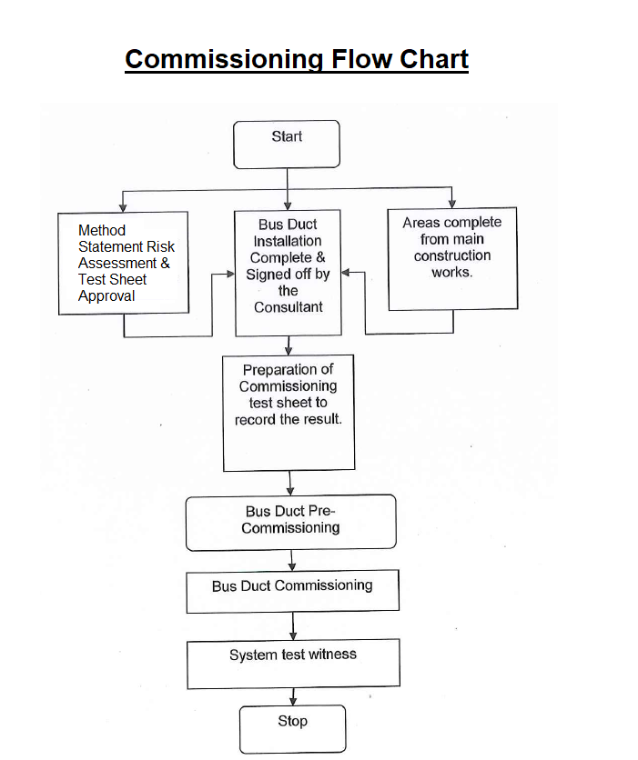
The purpose of this method statement is to outline the sequence and method of Testing & Commissioning of Bus Bar Trunking system.
Following tools and equipment shall be arranged before the activity.
Earth tester
Multimeter I Continuity tester
Megger Tester
Technician’s tools
Calibration certificates will be provided during testing and commissioning.
Important: Ensure equipment is disconnected from any possible source of electrical supply; disconnect I draw out ACB I MCCB feeder; switch off all tap off units, disconnect neutral and earth cables. Isolate the bus way run by disconnecting all connections to transformers, switchboards, meters, and so forth.
Pre-Commissioning Checks
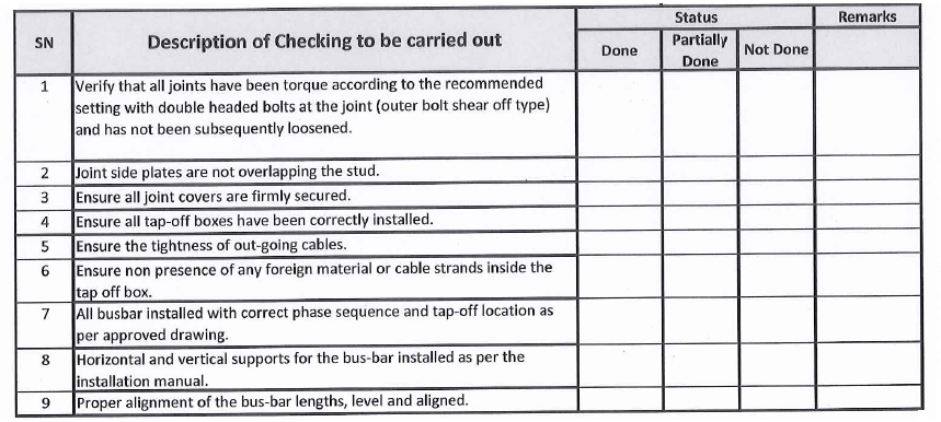
Pre commissioning checks will be carried out as indicated below, and recorded on the attached site pre-commissioning checks detailing the installation visual inspections as per attached checklist.
These checks are summarized as:
- Verify that all joints have been torque according to the recommended setting with double headed bolts at the joint (outer bolt shear off type) and has not been subsequently loosened.
- Joint side plates are not overlapping the stud.
- Ensure all joint covers are firmly secured.
- Ensure all tap off boxes have been correctly installed as instructed.
- Ensure the tightness of outgoing
- Ensure non presence of any foreign material or cable strands inside the Tap off box.
- All busbar installed with correct phase sequence and Tap off location as per approved drawing.
- Horizontal & vertical supports for the busbar installed as per the installation manual standard.
- Proper alignment of the bus-bar lengths, level and aligned.
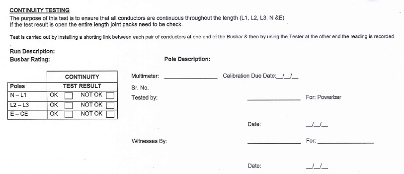
Conduct a continuity check on all phases/ground and neutral with a multi meter to ensure the bus way conductors are continuous throughout the length of the run.
Bus duct will be tested end to end with the readings taken at LV room
Results to be recorded on the bus duct record sheet.
Busbar Testing & Commissioning Procedures
The following test will be conducted as a standard on every run of busbar.
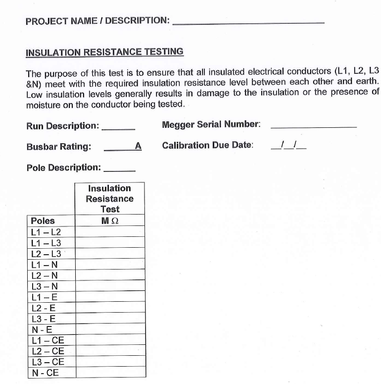
Insulation Resistance test:
This check is to verify the integrity of the insulation of the busbar following the installation and site conditions.
Insulation resistance will be carried out by IR tester at DC 1000 Volts to ensure that the system is free from short circuits and grounds.
The tests will be carried out Phase to Phase, Phases to Neutral and Phases to Earth and Neutral to earth.
Reading will vary widely between site due to length of run, humidity etc.
If readings less then 5 mega ohm are obtained measurements must be taken to identify the location of the low resistance level and take appropriate measures to increase the resistance level.
This test should only be carried out by competent personnel.
Note: In order to avoid nuisance in megger readings, remember to open circuit all the controls wiring inside the switchboard where busbar flange is connected.
Results to be recorded on the bus duct record sheet.
Verify system phasing:
Verify that the system phasing matches the bus way phasing before reconnecting all connections to transformers, switchboards, meter, and so forth.
Torgue testing
Check all joints for tightness as per manufacture’s torquing recommendation:
Provide scaffolding or ladder for easy access on joints to be tightened.
Remove the dust cap.
A double headed torque indicating bolt is provided to ensure that proper installation torque is achieved.
Initially the bolt can be tightened with a standard spanner, if it has to be removed in future, the re tightening torque, using a torque wrench 50 – 60 ft pounds.
Fall away instruction tags are furnished on the torque indicating bolt heads to allow for visual inspection from a distance.
When the proper torque value is achieved, the top bolt head will shear off and allow the tag to fall to the floor.
Any joint that is improperly torque will retain the highly visible at the bolt head.
Re fix the dust cap.
Move to the next joint and perform the same procedure.
Recheck of Insulation resistance:
Re – check the Insulation Resistance test after torquing of the busbar joints, to be carried out as described under Insulation resistance test section.
Functional test of Circuit Breaker:
- Check the operation of MCCB.
- Check the trip function of MCCB.
Energizing Process:
Prior to energizing perform all below checks:
Ensure all connections to the busbar I tap offs have been disconnected.
When reconnecting the system prior to energization ensure correct phase rotation is achieved by testing prior to energizing the supply.
Ensure all tap offs are turned off again prior to energizing.
Only authorized, competent personnel should energize electrical circuits in line with switching procedure and permit to work forms provided by the site supervisor.
The main supply switch to the busbar is to be energized first. The protection settings should be at the circuit breakers minimum protection level.
Following the successful closing off the supply breaker, close the circuit breaker(s) supplying the connected loads (via Tap-offs) one by one.
Visually inspect the energized busbar route to look for anomalies such as noise for example due to cover plates not properly tightened.

Installation Completion Inspection Check List
- Each Busbar piece has been Meggered before Installation?
- Each Busbar piece has been Meggered After Installation?
- All megger test reports handed over to testing engineer?
- Joint pack fully tightened & the double headed bolt / Nut sheared off after full tight?
- Are the joint side plates overlapping the stud?
- Are the Tap off box clamps fixed properly as per the Installation Manual?
- Are all Joint covers has been fixed matching the holes and tightened?
- Are all busbar generally clean and tidy and free from any dust / liquid?
- Are the Horizontal supports for the busbar installed as per the installation manual standard?
- Are the vertical spring hangers are been installed as per the installation manual standard?
- Are there any supports installed on the joint packs?
- Are any joint packs installed along the slab?
Pre Commissioning and commissioning Checklists