


The electrical energy is almost exclusively generated, transmitted and distributed in the form of alternating current. Therefore, the question of power factor immediately comes into picture. Most of the loads (e.g. induction motors, arc lamps) are inductive in nature and hence have low lagging power factor.
Low power factor is highly undesirable as it causes an increase in current, resulting in additional losses of active power in all the elements of power system from power station generator down to the utilization devices.
In order to ensure most favorable conditions for a supply system from engineering and economical standpoint, it is important to have power factor as close to unity as possible.
Methods of Power Factor Improvement
Power Factor is the cosine of angle between voltage and current in an A.C circuit.
As you are aware there is always a phase difference φ between voltage and current.
The term cos φ is called the power factor of the circuit.
Lagging Power Factor: If the circuit is inductive, the current lags behind the voltage and the power factor is referred to as lagging.
Leading Power Factor: In a capacitive circuit, current leads the voltage and power factor is said to be leading.
Consider an inductive circuit taking a lagging current (I) from supply voltage (V); the angle of lag being φ.
The phasor diagram of the circuit is shown in below Figure.
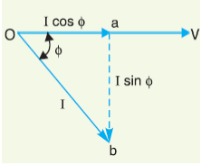

The circuit current (I) can be resolved into two perpendicular components, namely:
(a) I cos φ in phase with V
(b) I sin φ 90o out of phase with V
The component I cos φ is known as active or wattful component, whereas component I sin φ is called the reactive or wattless component.
Reactive component is a measure of the power factor.
If the reactive component is small, the phase angle φ is small and hence power factor cos φ will be high.
Therefore, a circuit having small reactive current (i.e., I sin φ) will have high power factor and vice-versa.
It may be noted that value of power factor can never be more than unity.
Lagging & Leading Power Factors
It is a usual practice to attach the word ‘lagging’ or ‘leading’ with the numerical value of power factor to signify whether the current lags or leads the voltage.
Thus if the circuit has a p.f. of 0.5 and the current lags the voltage, we generally write p.f. as 0.5 lagging.
Sometimes power factor is expressed as a percentage.
Thus 0.8 lagging power factor may be expressed as 80% lagging.
The Power Triangle & Power Factor Correction
The analysis of power factor can also be made in terms of power drawn by the A.C circuit. If each side of the current triangle OAB as shown in below figure is multiplied by voltage V, then we get the power triangle OAB.
where:
OA = VI cos φ and represents the active power in watts or kW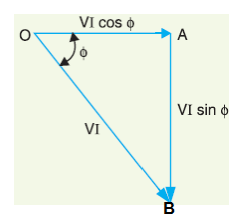

AB = VI sin φ and represents the reactive power in VAR or kVAR
OB = VI and represents the apparent power in VA or kVA
The following points may be noted from the power triangle:
(i) The apparent power in an a.c. circuit has two components viz., active and reactive power at right angles to each other.
OB2 = OA2 + AB2 Or (apparent power)2 = (active power)2 + (reactive power)2 Or (kVA)2 = (kW) 2 + (kVAR) 2
(ii) Power factor, cos φ = OA/OB = Active Power/Reactive Power = kW/kVA
Thus the power factor of a circuit may also be defined as the ratio of active power to the Apparent power.
This is a perfectly general definition and can be applied to all cases, whatever be the waveform.
(iii) The lagging reactive power is responsible for the low power factor.
It is clear from the Power Triangle that smaller the reactive power component, the higher is the power factor of the circuit.
kVAR = kVA sin φ / cos φ
∴ kVAR = kW tan φ
(iv) For leading currents, the power triangle becomes reversed.
This fact provides a key to the power factor improvement.
If a device taking leading reactive power (e.g. capacitor) is connected in parallel with the load, then the lagging reactive power of the load will be partly neutralized, thus improving the power factor of the load.
Representation / Formula Of Power Factor
The power factor of a circuit can be defined in one of the following three ways:
- Power Factor = cos φ = cosine of angle between V & I
- Power Factor = R/Z = Resistance / Impedance
- Power Factor = VIcos φ/ VI = Active Power / Apparent Power
Causes of Low Power Factor
Following are the causes of low power factor:
- Most of the a.c. motors are of induction type (1φ and 3φ induction motors) which have low lagging power factor. These motors work at a power factor 40 which is extremely small on light load (0.2 to 0.3) and rises to 0.8 or 0.9 at full load.
- Arc lamps, electric discharge lamps and industrial heating furnaces operate at low lagging power factor.
- The load on the power system is varying; being high during morning and evening and low at other times. During low load period, supply voltage is increased which increases the magnetization current. This results in the decreased power factor.
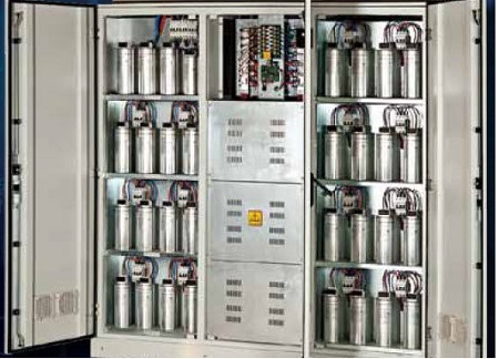
Power Factor Correction & Improvement using Capacitor Bank
The low power factor is mainly due to the fact that most of the power loads are inductive and, therefore, take lagging currents.
In order to improve the power factor, some device taking leading power should be connected in parallel with the load.
One of such devices can be a capacitor.
The capacitor draws a leading current and partly or completely neutralizes the lagging reactive component of load current.
This raises the power factor of the load.

Normally, the power factor of the whole load on a large generating station is in the region of 0.8 to 0.9.
However, sometimes it is lower and in such cases it is generally desirable to take special steps to improve the power factor.
This can be achieved by the following equipment:
- Static Capacitors
- Synchronous Condenser
- Phase Advancers
Static Capacitor
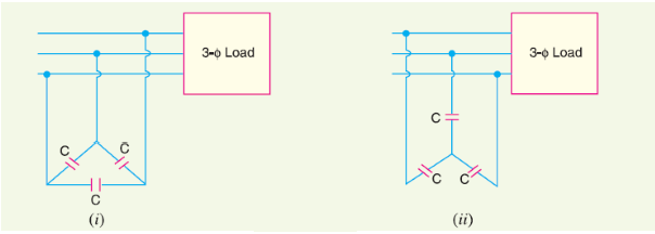
The power factor can be improved by connecting capacitors in parallel with the equipment operating at lagging power factor.
Capacitor draws a leading current and partly or completely neutralizes the lagging reactive component of load current.
This raises the power factor of the load. For three-phase loads, the capacitors can be connected in delta or star as shown below.
Static capacitors are invariably used for power factor improvement in factories.

Advantages of Static Capacitors
- They have low losses.
- They require little maintenance as there are no rotating parts.
- They can be easily installed as they are light and require no foundation.
- They can work under ordinary atmospheric conditions.
Disadvantages of Static Capacitors:
- They have short service life ranging from 8 to 10 years.
- They are easily damaged if the voltage exceeds the rated value.
- Once the capacitors are damaged, their repair is uneconomical.
Synchronous Condenser Power Factor Improvement:
A synchronous motor takes a leading current when over-excited and, therefore, behaves as a capacitor.
An over-excited synchronous motor running on no load is known as synchronous condenser.
When such a machine is connected in parallel with the supply, it takes a leading current which partly neutralizes the lagging reactive component of the load.
Thus the power factor is improved.
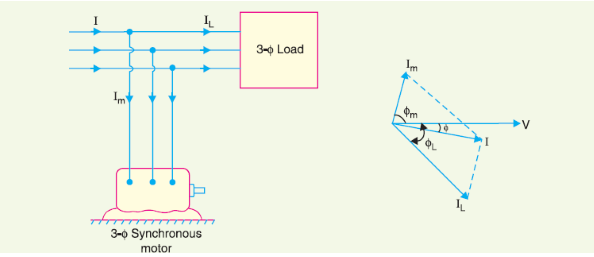

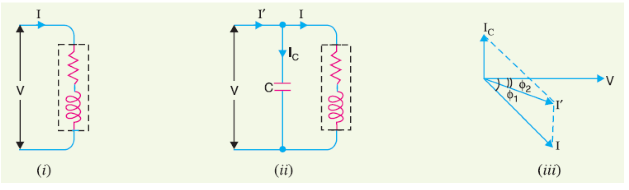
Above figure shows the power factor improvement by synchronous condenser method.
The 3φ load takes current IL at low lagging power factor cos φL.
Synchronous condenser takes a current Im which leads the voltage by an angle φm.
The resultant current I is the phasor sum of Im and IL and lags behind the voltage by an angle φ.
It is clear that φ is less than φL so that cos φ is greater than cos φL.
Thus the power factor is increased from cos φL to cos φ. Synchronous condensers are generally used at major bulk supply substations for power factor improvement.
Advantages of Synchronous Condenser Power Factor Improvement
- By varying the field excitation, the magnitude of current drawn by the motor can be changed by any amount. This helps in achieving step less control of power factor.
- The motor windings have high thermal stability to short circuit currents.
- The faults can be removed easily.
Disadvantages of Synchronous Condenser Power Factor Improvement
- There are considerable losses in the motor.
- The maintenance cost is high.
- It produces noise.
- Except in sizes above 500 kVA, the cost is greater than that of static capacitors of the same rating.
- As a synchronous motor has no self-starting torque, therefore, an auxiliary equipment has to be provided for this purpose.
Phase Advancers for Power Factor Improvement
Phase advancers are used to improve the power factor of induction motors.
The low power factor of an induction motor is due to the fact that its stator winding draws exciting current which lags behind the supply voltage by 90o.
If the exciting ampere turns can be provided from some other A.C source, then the stator winding will be relieved of exciting current and the power factor of the motor can be improved.
This job is accomplished by the phase advancer which is simply an A.C exciter.
The phase advancer is mounted on the same shaft as the main motor and is connected in the rotor circuit of the motor.
It provides exciting ampere turns to the rotor circuit at slip frequency.
By providing more ampere turns than required, the induction motor can be made to operate on leading power factor like an over-excited synchronous motor.
Phase advancers have two principal advantages.
Firstly, as the exciting ampere turns are supplied at slip frequency, therefore, lagging kVAR drawn by the motor are considerably reduced.
Secondly, Phase advancer can be conveniently used where the use of synchronous motors is inadmissible.
However, the major disadvantage of phase advancers is that they are not economical for motors below 200 H.P.