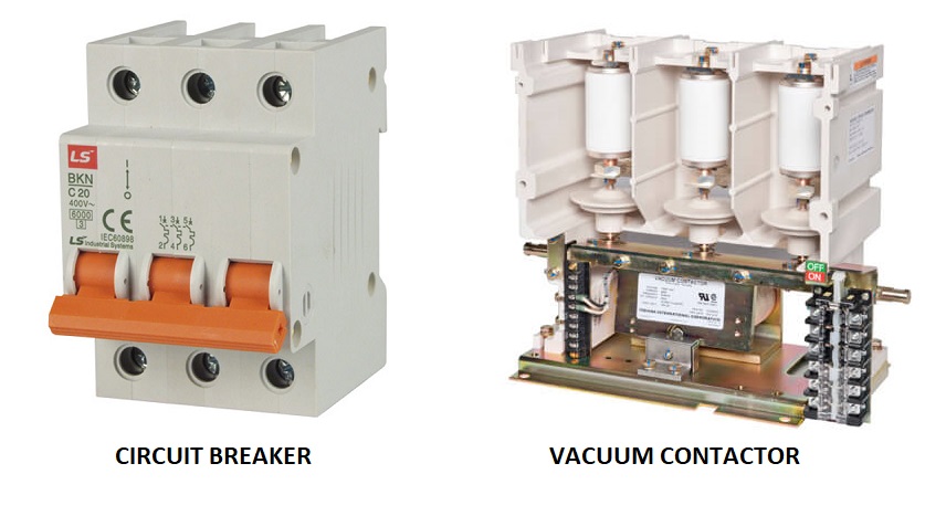
To compare the application of medium-voltage circuit breakers and of fused contactors, we must understand the basic characteristics of each switching technology.
The below table shows the major characteristics of medium-voltage circuit breakers and medium-voltage fused contactors that influence the application.
Of course, the table entries are generalized, and the information varies by the voltage and current ratings of the equipment. However, the table is valid for an overall understanding. From the data in the table, Siemens makes these observations:
Medium-voltage circuit breakers are favored when:
Typical loads include transformers, capacitors, larger motors, generators or distribution feeders
Ratings required exceed those of vacuum contactors (400 A or 720 A at up to 7.2 kV)
Continuous load current is high (e.g., larger transformers, larger motors)
Switching is not very frequent (e.g., weekly or monthly); high endurance (1,000s of operations) is satisfactory
Process continuity is critical (e.g., no time for fuse replacement)
Reduced-voltage (RV) starting is not needed (RV starting complicates switchgear bus arrangements).
Medium-voltage NEMA Class E2 controllers (fused contactors) are favored when:
- Typical loads include motors or smaller transformers
- Continuous load current is low or moderate (e.g., smaller motors or transformers)
- Switching is very frequent (e.g., daily or several times per day); very high endurance (100,000s of operations) is
needed - Process continuity is compatible with fuse replacement time
- Reduced-voltage starting is needed to reduce starting duty (and voltage fluctuation) on system.

Historically, circuit breakers have been used for medium voltage motors in certain industries, especially in utility
generating stations.
As these stations have aged, and station operation has changed from base-load to peaking service, many of these motor-starting circuit breakers have experienced total operations well in excess of the endurance required by the ANSI/IEEE standards.
As a result, these applications have had higher maintenance costs than if medium-voltage fused contactors had been used originally. In contrast, users in the process industries have long favored the use of fused contactors for such applications, and have enjoyed long service with lower maintenance costs.
When applied properly, both medium-voltage circuit breakers and medium-voltage fused contactors should provide decades of reliable service. Applied incorrectly, either can lead to major headaches.
|
Characteristic |
Circuit breaker |
Contactor (NEMA E2 with fuses) |
|
Continuous current |
High (1,200 A, 2,000 A, 3,000 A or 4,000 A) |
Moderate (400 A enclosed – NEMA size H3, or 720 A enclosed – NEMA size H6) in SIMOVAC controller |
|
Switching capability |
Switch currents from very low (magnetizing) values to full system short-circuit current |
Switch currents from very low (magnetizing) values to interrupting capability of vacuum contactor without fuses (at least 10 x continuous rating)
Fuses operate for currents higher than the interrupting capability of the vacuum contactor alone, up to the interrupting capacity of the fuse |
|
Endurance – mechanical |
High (typically 10,000 operations) (refer to ANSI/IEEE C37.06) |
Very high, 750,000 operations for 400 A and 400,000 for 720A |
|
Endurance – electrical |
High For vacuum, typically 10,000 operations at rated continuous current For vacuum, typically 30 to 100 operations at full short-circuit rating |
Very high
Switching continuous current, 400,000 operations for 400A or 200,000 operations for 720 A Switching short-circuit current, endurance data not established in NEMA or UL standards; short-circuit current interruption requires replacement of current-limiting fuses |
| Application limitations | Not appropriate for very high endurance applications | Well suited for very frequent switching operations |
|
Operation |
Electrically operated (manual operation for maintenance or emergency) |
Electrically operated only |
|
Control scheme |
Mechanically latched – circuit breaker remains closed on loss of system voltage |
Usually magnetically held – vacuum contactor opens on loss of system voltage; vacuum contactor will close automatically on system voltage return with two-wire control; manual restart required on system voltage return with three-wire control Latched contactors are available |
| Overcurrent/
short-circuit protection |
Requires protective relays |
Requires protective relays for overload protection and current- limiting fuses for short-circuit protection |
| Short-circuit let-through energy | High (three to five cycles or more of short-circuit current) | Low (current-limiting fuses interrupt in 1/4 cycle for highest short-circuit currents, and peak magnitude is limited) |
| Remote operation | Well suited | Well suited |
|
Control power |
Control power needed for protective relays, circuit breaker operation and space heaters (if present) | Control power usually provided by control power transformer
(CPT) incorporated in the controller |
|
Construction |
Drawout, if metal-clad (ANSI/IEEE C37.20.2) Stationary, if metal-enclosed (ANSI/IEEE C37.20.3) |
Drawout or stationary |
|
Space requirements |
Larger enclosure NEC® required workspace equal |
Smaller enclosure
NEC® required workspace equal Rear access not required |
| Purchase cost | Relatively high | Moderate |
|
Maintenance |
Medium (long maintenance intervals, need to clean insulation) |
Low (simple mechanism, need to clean insulation, replace fuses) |
Source: Siemens Technical Paper
Discover more from Electrical Engineering 123
Subscribe to get the latest posts sent to your email.

