
The electrical method statement below provides the brief steps to be carried out during the AC High voltage testing.
Method statement applies to the testing of 11 KV switchgear.
Testing and commissioning engineer / responsible person shall obtain all necessary clearances and safety document from concern authorities. He shall ensure the work is done as per approved method statement and inspection testing plan / schedule. Also to ensure that necessary toolbox talks are conducted and recorded.
Electrical technician shall perform the work under the strict supervision of testing and commissioning engineer.
HSE officer shall identify all the associated hazards and coordinate with the competent person to properly control these hazards.
Preparatory Works
Before the commencement of any electrical testing and commissioning tasks following checks to be completed:
Make sure the work area is clean and all floor openings are closed.
Barricade the testing area by using red and white chain and warning signs to be displayed as necessary.
Only authorized personnel related to testing activities shall be allowed to enter the barricaded area, they must wear all the mandatory personal protective equipment PPE.
Make sure that all the testing equipment and instruments are calibrated and valid calibration certificates are available at the testing site.
Make sure all connections are made using approved and suitable clamps etc.
Ensure the proper earthing of the switchgear, and make sure that the Discharge Rod is connected with the Earth.
HV Testing Procedure
Ensure NO power cables are connected in 11kV switchgear.
Prior to start the test on BUSBAR all breakers to be kept in CLOSE condition except Bus Section breaker.
Ensure the Bus-Section Breaker in OPEN condition.
Ensure the Bus Earth Switch & Voltage transformers are in ISOLATED or OPEN condition.
Ensure the CT Secondary Circuits are Shorted and earthed.
Select +K01 as a reference panel for applying the HV at Busbar.
Select the R Phase for the testing and remaining two phases Y & B to be shorted with earth.
Apply 5kV DC Voltage between ‘R’ Phase of +K01 and earth through the calibrated IR Tester for a time duration of 1 MIN.
All the Values to be recorded as shown in the test format.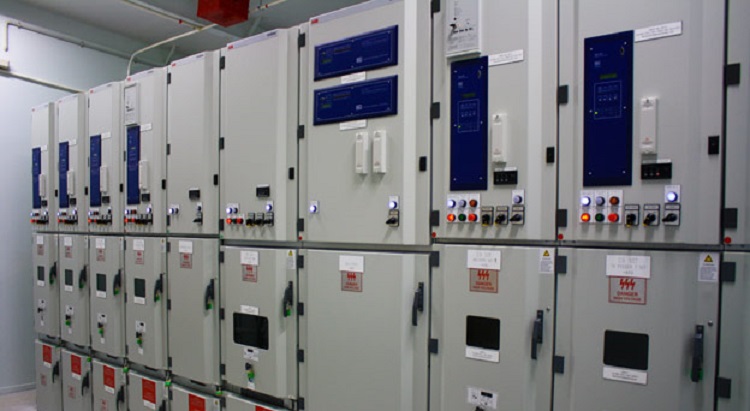
Discharge the tested Phase by using the discharge rod & Safety gloves.
Repeat the above procedure for the remaining two phases say Y & B.
Ensure the Healthiness of the 11kV SWGR insulation through the IR Test Values.
Ensure the Proper earthing of HV Test equipment prior to start the HV Test.
Select the R Phase for the testing and remaining two phases Y & B to be shorted with earth.
Apply 3kV AC Voltage on R-Ph at Busbar.
Ensure the healthiness of all HV Indicator ( CAPDIS) mounted at 11kV SWGR.
Increase the AC Voltage smoothly to 80% of FAT Value( Power Frequency Voltage test ) or else say 25kV on R-Ph for the time duration of 1 Min.
Record the Values as shown in the approved test format & ensure that switchgear is withstanding for the test value.
Reduce the Voltage gradually to zero.
Discharge the tested phase in safe manner by using the discharge rod with the HV safety gloves.
Test to be carried out for the remaining two phases in same manner (i.e. above steps).
Attachments:
Risk Assessment
SAT Formats
Important: Above method is given for reference purpose the testing of HV equipment must be done by competent personnel by following the specific and approved procedures.
Sharing is caring:

Discover more from Electrical Engineering 123
Subscribe to get the latest posts sent to your email.