
All electrical checks and tests shall be conducted as per the manufacturer’s drawings/manuals, relevant codes of installation and below given commissioning check lists.
The electrical installer/contractor shall also carry out additional tests if called for in the project electrical specifications.
Contractor shall carry out insulation resistance tests by meggers of following rating.
(a) Control circuits up to 220 V – 500 V megger
(b) Power circuits up to 11 KV – 1000 V megger
(c) Power circuits above 11 KV to 33 KV – 2500 V megger
(d) Power circuits above 33 KV – 5000 V megger
Testing of Cabling System
Carry out the tests as specified in Cable Installation Notes which forms part of cable specification.
Earthing and Lightning Protection System
Ensure the continuity of all conductors and joints. Earth continuity and earth resistance measurement tests shall be performed at places indicated by the client, at no additional cost.
Lighting System: Tests on the lighting system shall be conducted as specified in Lighting Installation Notes.
Test Records
The client authorised representative shall be present during every test as called for by the client.
Electrical contractor shall record all test values and furnish the required copies of the test data to the client. Electrical circuits and equipment shall be energized or used at nominal operating voltage after such reports are accepted as satisfactory by the client.
Contractor shall make available the following Testing and Commissioning equipment for testing and commissioning of various equipment in the plant :
- 500V and 1000V hand operated meggers.
- 5000V/2500V motor operated meggers.
- Earth resistivity testing equipment.
- Phase sequence indicators.
- Frequency meters.
- Micrometers
- High potential testing sets suitable for testing cables upto 33 kV grade complete with transformer, rectifier stack, instruments and control.
- Miscellaneous instruments/accessories like clip-on ammeters, voltmeters, watt meters, multi-meters, power factor-meters, time-interval meters, single-phase and three-phase variacs, portable transformers, switches etc.
- Continuity testers.
- Primary injection equipment.
- Secondary injection testing kit.
- Insulating oil breakdown test set with accessories.
- Equipment for measuring the thermal resistivity of the soil.
- Transformer oil filtration equipment.
- Relay test kits.
- Breaker timing device for Circuit breaker opening/closing time measurement.
- CT & VT testing apparatus.
- Low resistance measuring instrument.
- Partial discharge measuring equipment.
Electrical Precommissioning Checklists
Switchgears Pre-Commissioning
Before commissioning any switchgear panel, circuit breaker, motor starters, etc., the following points must be checked and ensured for safe energizing of the switchboard:
Check that the erection of equipment to be commissioned is complete in all respect with its auxiliaries and all other mountings including earthing.
Openings in floor within and outside panels have been sealed off. All cover and door gaskets are intact to make enclosure vermin proof. Check also the wiring of the switchgear panel as per approved final vendor drawing.
Check that all the metering instruments have been checked and calibrated.
Indicating lamps are healthy and are in position. All power and control fuses, MCBs are of proper rating and operational.
Panel is supplied from correct level of voltage source.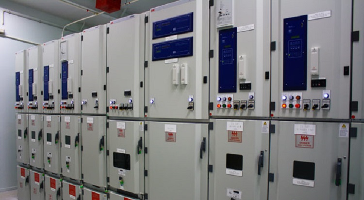
Check termination of power cable and its size and type.
Check if unusual stress coming on cable glands and terminations due to improper bending and support of cable at the PCC/MCC entry.
Check all mechanical operations – like racking in/out of breaker, drawing in/out of MCC modules, operation of all position indicating limit switches for breakers, manual spring charging of breaker, mechanical on/off of breaker, spring charging limit switch, etc.
Check all safety interlocks.
Check lubrication of operating/moving parts of breakers/MCC modules.
Check scrapping earth connection for breaker.
Check spring charging by motor and spring charging time.
Check that the polarity test and ratio test of all the P.Ts and C.Ts is done and phase sequence test of C.Ts conforms to the correct vector group connections.
Wiring continuity and correctness are ensured in the protection and measurement circuits. Polarity of D.C. battery supply for all the panels shall be checked.
Also check that the high voltage test of circuit breaker, bus bars etc., have been conducted and certificates approved by site in charge.
Check that all the protective relays including thermal overload relays have been tested for secondary injection tests and operation of all the current and voltage operated relays has been tested.
Primary injection tests are to be carried out for Cable differential protection, Restricted Earth fault protection, etc., at full/reduced current to ensure total wiring correctness.
Simulation tests to check all protection, alarm and annunciation systems are functioning as per required settings.
Check that all protections of breakers & MCC (of each module) are as per approved final vendor drawing.
Check all interlocks.
Check that I.R. values have been recorded for bus bars, circuit breaker, control wiring and potential transformers. Joint resistance of bus bars have been recorded and found to be satisfactory.
All the surroundings and panels have been cleaned and temporary earth leads have been removed.
Check all covers closed properly before energizing the panels.
Check control supply voltage is proper.
Check space heater operation.
Check for chattering of any relay or contactor.
Check anti-pumping feature of breaker.
Check operation of mechanical counter of the breaker if provided.
Transformer Pre Commissioning Checks
Before commissioning any transformer the following points must be checked and ensured for safe energization of the transformer:
Check that all the accessories have been fixed properly. The transformer dehydration is over and results are satisfactory and approved by the Client.
Check grounding of marshalling box, tap changer gear. Check earth bus inside the bus duct & grounding of the bus duct enclosure. Check system grounding on the H.V. & L.V. side.
Check that the operations of off-load tap changer on all the tap positions is satisfactory. The mechanical parts of the off load tap changer are lubricated.
Break shoes are O.K. Check for Motor IR values and check the tap position mechanical indicator on the transformer. Tap changer limit switch are operating alright on the maximum and minimum tap position & Off-load tap changer contact pressure and resistance is as per manufacturer’s recommendations.
Check that all the metering equipment has been tested. Polarity test of P.Ts and transformer winding is alright. Phase sequence and connections have been checked for proper vector group. Check Neutral C.T. connections.
Check that the ratio test and winding resistance on all the tap positions is alright.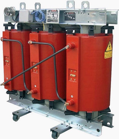
Check that gaps of arcing horns for the bushings are alright and earth connections for the surge diverters have been checked.
Check that the winding temperature thermometer pockets. That winding settings on dial gauges are O.K.
Check that the simulation test for all the alarm, annunciation and trip circuits have been checked and are alright. Check the stability of restricted earth fault for out of zone fault.
Check that the insulation resistance of all the control circuits and IR value of the transformer windings and all the incoming and outgoing cables have been checked with 1000V megger.
Check that the setting of all the protective relays is at the desired valve and D.C. Trip supply is available.
Motor Pre Commissioning Checklist
Check motor mounting.
Check motor is rotating freely by manual effort.
Check motor cooling fan installed properly.
Check motor body is grounded at two points. Check terminal box grounding.
Check all components installed as per approved final vendor drawing.
Check motor power supply cable connected to proper level of voltage.
Check termination of motor cable at motor end as well as at MCC/ Switchgear end.
Check terminal box cover closed properly and unused entries plugged.
Check terminations at auxiliary terminal box and unused entries plugged.
Check continuity of motor cable.
Check ‘Megger’ value of motor and power supply cable.
Check alignment of motor with the driven equipment. To ensure no undue force is imposed on bearings.
Check greasing of bearings at both ends.
Check endplay in bearings.
Check oil level in gearbox.
Check bimetallic relay setting at MCC module.
For breaker fed motor check all relay settings and CT polarity.
Check Local Control Station is properly wired and complete with all necessary control and indication. Check enclosure of local control station for hazardous atmosphere.
Check wiring of all the interlocks for proper wiring.
Precommissioning Checks for Battery and Battery charger
Check mounting or battery bank and battery charger.
Check power cable termination/glands.
Check control cable termination, interlock, wiring, loose connections.
Check earthing of battery charger panel.
Check all safety interlocks.
Check specific gravity of electrolyte in battery bank.
Check battery voltage in charged condition.
Check rating and type of all power and control circuit fuses.
Check the `Megger’ value of power and control circuit.
Check supply voltage of battery charger.
Check operation of battery charger and load on the charger. Check all annunciations under stimulated condition.
Check changeover from mains supply to battery and vice versa.
Check DC distribution board mounting, earthing.
Check feeder schedule of DC distribution board and their correct description.
Check all cable terminations/glands.
Check ‘Megger’ value.
Check all safety interlocks.
Check incoming supply to DC distribution board.
Check all fuse ratings in DC distribution.
Sharing is caring:

Discover more from Electrical Engineering 123
Subscribe to get the latest posts sent to your email.