
The purpose of this method statement is to define the sequence and working methodology of the positioning and installation of UPS system especially Chloride 80 Net System.
Upon receipt of the UPS system and accessories at site, necessary precautions shall be taken for unloading, shifting & storage, as follows:
UPS system and components delivered at site shall be carefully off-loaded by deploying necessary manpower and equipment in such a manner that no damage is caused to UPS system and components.
Uncrate, unpack and remove the panel from its timber base. Care must be taken to protect the panel from unnecessary scratches or bends on the panels.
Material inspection request should be raised for inspection and approval with all relevant supporting documents.
The UPS system and components shall be checked visually/mechanically for any damage during the shipment or movement to site.
UPS system and components shall be stored as per the storage condition listed on both packing and directly on the goods.
Material found not suitable for site use shall be removed from site immediately.
All the equipment must be kept upright at all times and handled with care, damage may be caused if dropped or subjected to severe impact. When moving the Equipment with a forklift, secure it against tilting.
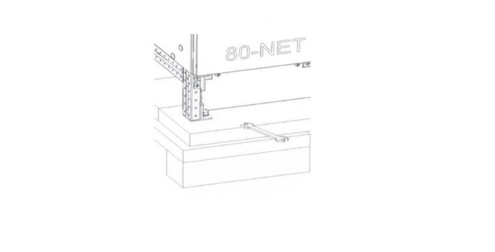
The utmost care shall be taken when removing the packaging in order to avoid damaging the equipment. Check all packaging materials to ensure that no items are discarded. Once the packaging has been removed, the UPS shall be taken off the pallet by removing the retaining screws, as illustrated in below image, and lifting it off using a fork lift (max width between forks – 540mm – Ref EN 1757).
Note that the retaining brackets must not be unscrewed from the UPS feet.
Also note, that when moving the pallet, the maximum distance between forks is 690 mm.
Pre Installation Requirements
Prior to commencement of installation it shall be ensured that all previous activities have been completed & the area is released to start the installation of UPS.
Work shall not proceed prior to the approval of shop drawing, and all other relevant/necessary approvals.
Obtain the clearance from main contractor to install the equipment’s.
Check for the safe access to carry out the UPS installation works.
Coordinate with the other trades for any clashes.
Check the is UPS room is airconditioned.
Ensure equipment and its components are all in accordance with the approved material submittals.
Make sure that adequate number of tradesman and proper tools are available at site.
UPS Installation Procedure
The UPS must be installed vertically, on a level and even surface and in an area protected from extremes of temperature, water and Do not stack units and do not place objects on top of them.
The operating temperature range of the UPS is o °C to 40°C.
Ideal environmental temperature range is 15 °C to 25 °C. The battery life is defined at 20°C. Each increment of 10 °C above 25 °C reduces the expected life by 50%.
The area must have sufficient space for installation manoeuvres to be carried out Access doors must be wide enough to permit unobstructed transport of the device.
Outer overall dimensions of the UPS are given in the final data table.
Leave a minimum distance of 500mm between the top of the cabinet and the Ceiling of the installation area.
There are no restrictions to where you can position the UPS.
The rear of the machine can be positioned against a wall.
On machines with connecting cables at the rear, allow room for the curvature of the power cables.
Do no crush the cables against the wall.
Make sure the availability of space to perform maintenance operations from the front and from the top.
Note that the front panels open to an angle of 180°.
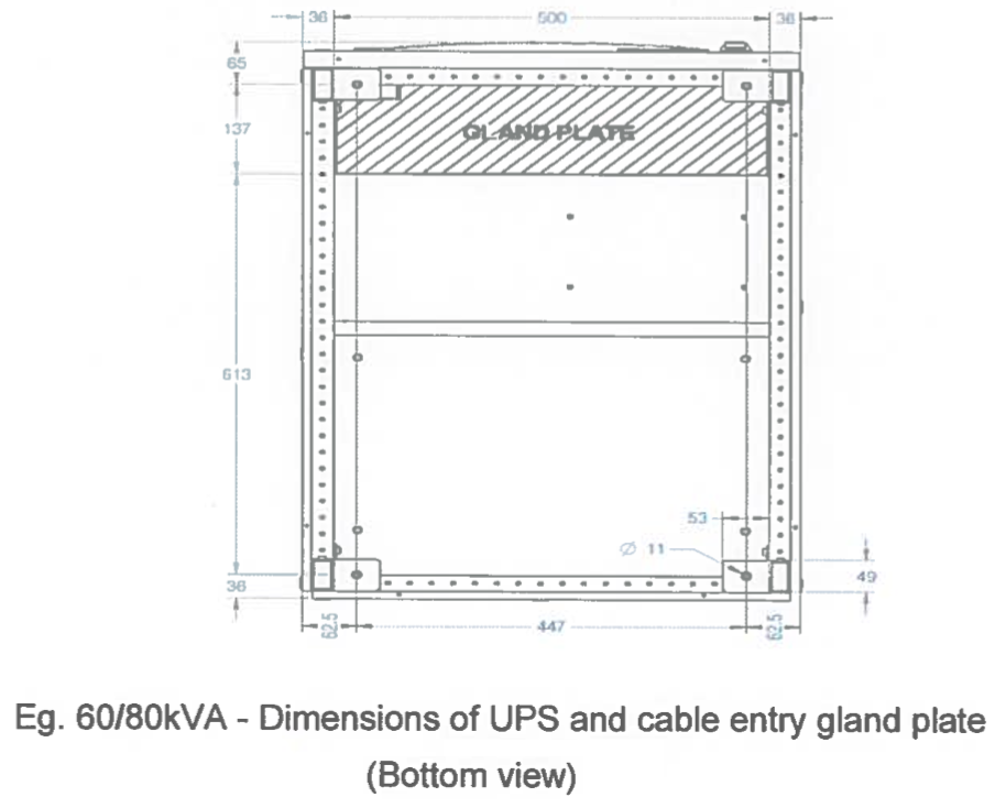
The floor on which the UPS will be installed must be level, flat and suitable for electrical equipment.
The floor must have a load bearing capacity which will support the weight of the UPS. The cable entry gland plates are illustrated below:
Installation of Cable Tray for pulling cables shall be carried out by coordinating with other system services as per approved shop drawings.
Prior to pulling of cable, check and ensure that there are no sharp edges/burrs in the raceways to prevent damage while pulling wires.
Cable shall be pulled for UPS system as per approved shop drawing.
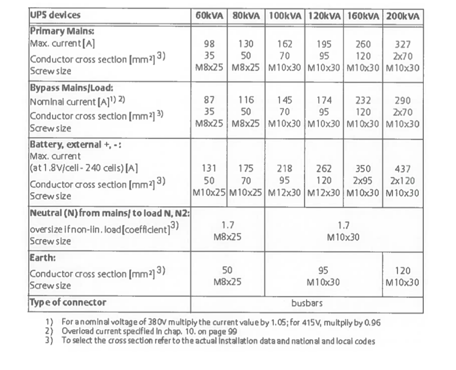
For external wiring requirements refer to Table below.
Refer to the national and local rules for the selection of the conductor size.
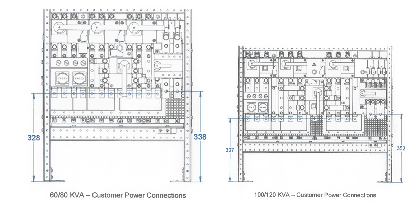
Connect the mains supply cables to the UPS terminals U, V, W, N. Connect the bypass mains supply cables to the UPS terminals U1, V1, W1, N.
Connect the load to UPS terminals U2, V2, W2, N. (see below image)
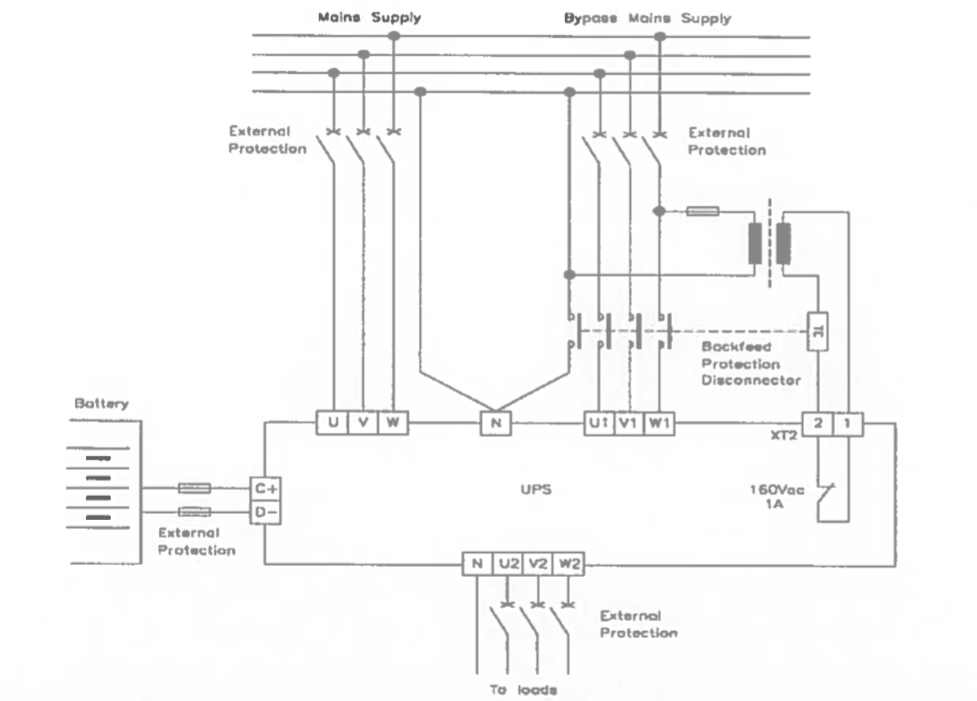
In the absence of a separate Bypass mains Supply, connect jumpers between U and U1, V and V1, Wand W1.
The cross section indicated in below Table refer to the following conditions:
- 70°C rated PVC copper cables;
- Cable routed in conduits for electrical installations. Separated conduits for each line;
- Air temperature in the conduits must not exceed 30°C;
- Cable lengths up to 30 m;
Important Notes:
Should there be any variation in the conditions it will be necessary to verify whether the cable dimensions satisfy the requirements of IEC 60287.
When selecting the cable it is important to take into account the voltage drop due to the cable length (if the voltage drop exceeds 3%, increase the cross section).
If the UPS supplies predominantly non-linear loads, the cross section of the PEN conductor must be oversized by a factor of 1,7 for 60-200kVA
To avoid electrical interferences:
- The routing of the power cables (primary input, bypass input, battery, output load cables) should be done in order to have separation between them,
- Routing of the communication and data lines cables should be done using proper conduits and they must be kept separated from all the power cables.
The cross section of the earth cables indicated in the above Table is indicative. It must be selected in accordance with the national and local rules and Coordinated with the upstream protection.
External electrical connections
In order to access the external electrical connections it is necessary to open the front door of the UPS and remove the secondary access panel (see below figure).
Connect the earth cable (PE) first.
Ensure that the UPS is isolated before removing panels. Power connections
The power connections (see figure below) on the front of the UPS are:
- U, V, W – MAINS INPUT
- U1, V1, W1 – BYPASS MAINS SUPPLY (only at the standard UPS type)
- N – NEUTRAL BAR (PEN/N) (COMMON TEST POINT FOR PRIMARY INPUT NEUTRAL, BYPASS INPUT NEUTRAL AND OUTPUT NEUTRAL)
- U2, V2, W2 – UPS OUTPUT TO LOAD
- D-, C+- BATTERY TERMINALS
- EARTH CONNECTION (PE)
Please Note that:
In case of a TN-C distribution system, connect an insulated jumper between UPS ground and the UPS Neutral connector.
Refer to local Standards and regulations for the correct jumper cross section. Connect the mains supply PEN cable to the UPS Neutral connector (N).
Ensure that the mains and load conductors are connected to the UPS as a clockwise (right hand) 3 phase system.

Battery cabinets shall be installed alongside the UPS as per the drawing (note The Battery terminals are located on the right hand side of the UPS).
Connecting the UPS Batteries
The UPS is equipped with a separating device for the battery DC power connection.
Before connecting the batteries, please read the notice and warning label on the UPS or battery cubicle.
Notice
Full safety instructions concerning the use and maintenance of UPS batteries are provided in the appropriate battery manufacturers’ manuals. The battery safety information contained in this section relates to key considerations which must be taken into account during the installation design process, and may affect the design outcome, depending on localized conditions.
Warning
Special care should be taken when working with the batteries associated with the Chloride 80-NET. When all batteries are connected together the overall voltage exceeds 500V.
It is most important to ensure that the batteries are installed separately, in a purpose-designed, lockable, dedicated battery cabinet or battery room.
Warning
In the event of malfunction, the battery shelves and/or cabinet chassis or battery frames may become live! Ensure correct polarity.
Connect the UPS and battery cabinets as per the drawing with specified cable.
Connect the earth cable (PE) before connecting the other cables.
Check the polarity of each shelf, making sure that the voltage is correct.
Connect the shelves to one another. Check polarity of each cabinet at the fuse holder.
Connections between battery cubicles and UPS
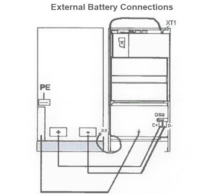
Connect the batteries with cables as suggested as per the above table to terminals + (positive pole) and – (negative pole), and in accordance with the connection diagram.
Connect the cable for the temperature sensor of the battery cabinet between terminals XT1.1 andXT1.2 of the UPS terminal block (refer figure below)
Shielded temperature sensor lines must be used between the UPS cabinet and the battery cabinet for EMC interference suppression as specified by IEC/EN 62040-2 Class RS. The shielding is to be connected to the UPS. Secure the sensor in the battery cabinet using a cable clamp or similar device.
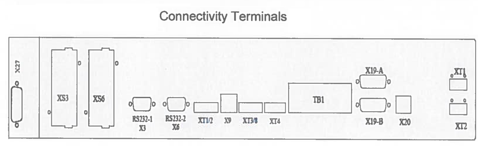
UPS system shall be connected to BMS system for monitoring as per specification. The Connectivity Terminals are shown below:
After the completion of the installation works including cable terminations, an Inspection request shall be raised for the UPS system installation for signature/acceptance to the client/consultant.
A remote alarm panel is available for displaying important individual UPS messages. The connection cable must not exceed 300 meters.
Installation Checklist for UPS Installation Works
Approved Materials/ Equipment’s/ Components used (MIR)
Installation is done as per approved shop drawings.
Check the elevation, orientation, plumbness & alignment are correct.
The panel assembly and installation according to manufacturer’s written instructions.
Check the panels supported rigidly with footings and grouted if required.
Check the component rating, size and type as per requirements.
The wiring system installed as per schematic diagram.
Check proper and correct torque as per manufacturer’s recommendations.
Check the accessibility for operation and maintenance.
Check the wiring for interfacing with BMS.
Check the wiring for remote alarm panel.
Check physical damage/holes cutout on panels.
Ensure manufacturer has certified the installation.
Sharing is caring:

Discover more from Electrical Engineering 123
Subscribe to get the latest posts sent to your email.