
This document defines the method for electrical house wiring for any kind of building or project in order to ensure that the works to be conducted at site are in compliance with the approved designs and approved materials.
You will need following tools before starting the house wiring:
- Measuring tape and setting out markers
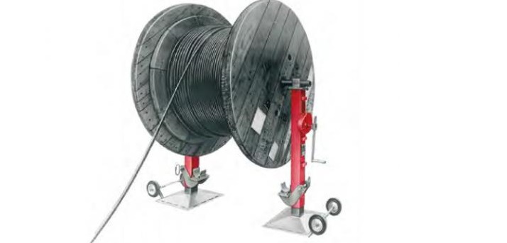
- Cable Drum / Cable Roller
- Hydraulic / Manual Crimping Tool
- Multi Tester / Cable Insulation Tester
- Light Trolley
- Hydraulic Cable Jack
- Electricians tool box
Handling & Storage
The raceway system material such as Power Cables and Wires should be according to the site requirement and in accordance with the approved/design drawing.
Material Controller will be responsible for the receiving of materials on site warehouse.
The supervisor and foreman will inspect all the materials delivered to the work place and ensure that these are the required materials and also for damage or defect.
Materials found not to be as per requirement or with damage or defect will be set aside. These will be properly labeled and returned to the warehouse. These will also be reported in a Non-Conformance Report to the QA/QC Engineer.
It should be noted that the materials used in this work area are of valuable nature and that they shall be stored in a secure location, clean / dry place and adequate covering by tarpaulin sheets to be provided to protect it from deposition of construction dust till they are finally shifted to their location and access to these materials shall be strictly controlled.
All electrical wiring materials should be properly stored as per manufacturer recommendation.
Preparation of Works
Ensure all shop drawings are “Issued for Construction” and were approved by the Consultant and that the latest revision of the relevant electrical wiring drawings is available at site.
Ensure all drawings are coordinated with other services and installations.
Also check and ensure that all the electrical containment for the power cables or wires is complete as per the drawing.
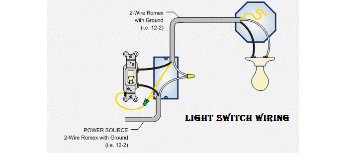
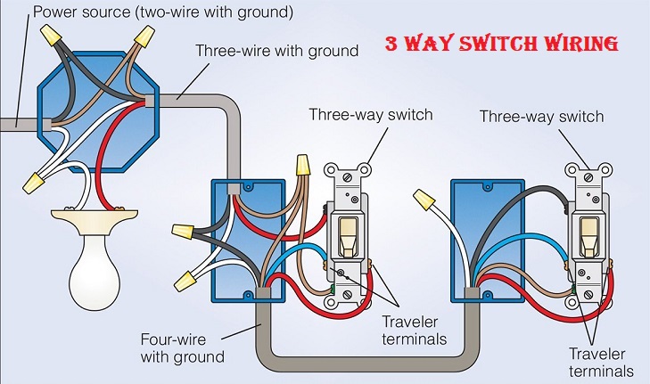
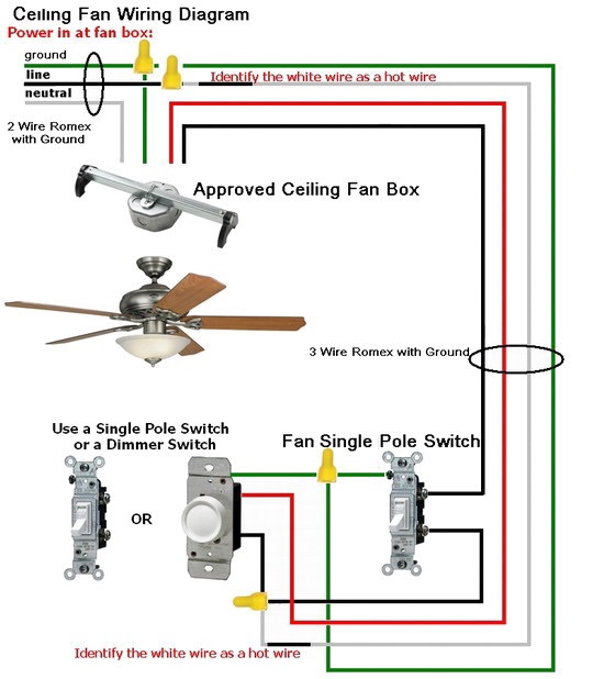
Electrical House Wiring of Power Cables & wires
Provide wooden block below the cable drum to prevent it from rolling and before removing the hoist cable.
Check the direction of arrow on the drum so that it is in the same direction as the pull.
Jack-up the cable drum by means of hydraulic jack enough to give clearance from the floor.
Remove the wooden cover of the cable drum.
Select the required pulling grip, when selecting a pulling grip, it is extremely important to select a grip of the correct type, size and maximum rated capacity. Measure the circumference of the cable and find the correct size.
Remove all steel binding straps, retaining battens and timbers. Remove any exposed projecting nails. Ensure that cable containment is cleared from any sharp edge to eliminate damage or scratches on the insulation of cables.
Install the cable roller on the cable tray on the entire cable laying area. Provide cable roller interval at 3 meters for straight run and corner cable roller on every change in direction.
Connect the pulling rope to the cable grip using shackle and provide signal on other end of the rope for cable pulling.
Ensure during cable pulling that cables are properly aligned and no cable twisting will occurs. Use cable lubricant as per the recommendation by the manufacturer to help pulling tensions down.
After the cable has reached the other end, measure the required length for termination to the Equipment or Distribution board. Provide adequate allowance for every termination point before cutting the cable at cable drum end.
Arrange the cable on the cable tray with approved cable spacing as per standards and specification.
Layout of cables must follow as per design / installation drawings.
Where cable trays pass through floor or walls of a specific fire resistance, install the approved fire stopping materials as per manufacturer’s recommendation.
After obtaining the measurement, cut the cable from the drum and separate each phase of the cable in preparation for another insulation test.
After cutting the cable separate each strand and performs for another initial insulation test. Record all the testing result.
After testing seal both end of the cable with PVC insulation tape. Provide proper cable identification and markings to prevent any obstruction and protection from any damage.
When work is complete, the work will be inspected and snagged by QA/QC Electrical Inspection team and any works found not compliant will be replaced or fixed before the final inspection is raised.
Ensure that all punch items have been cleared, all inspection records are signed and accepted by the client. Check that the signatures of the competent client inspector obtained where applicable and MEP Clearance can be given and the system is released for subsequent activities.
Electrical Wiring Cable Termination Procedure
Tools for the cutting and stripping of cable or wire for termination includes wire stripper/cutter tools and retractable knives.
Use of the wire stripper/cutter tool is preferred to the retractable knife for the stripping and cutting of cable or wire for safety reasons.
The wire stripper/cutter tool is used in the following manner for preparing cable or wire ends for termination:
Determine the correct cable core or wire size prior to inserting the cable core or wire ends into the tool head for stripping.
Squeeze the tool handles until the cable sheath or wire insulation is cut through to the metal.
Stripping of cable core or wire ends is then carried out by removing the cut cable sheath or insulation.
The cutting of the cable core or wire using the tool cutter is carried out by inserting the end into the tool head cutter blades and then squeezing the tool handles.
Where it is not possible, because of cable size or availability, the use of retractable knife is acceptable for wire stripper/cutter tool. It is important that in using this tool, care is taken in order to avoid injury.
Blade of knife should be retracted or covered with suitable protective cover when not in use, at all times.
Procedure for Cable Termination (Hand Crimp and Screwed Terminal for Cable below 35mm)
The final destination of the cores of each cable shall be obtained from the Connection Schedule.
Using this information the cores shall be routed in looms to their appropriate terminals.
At this point the core will be measured, cut and ferruled in such a manner that a core entering a terminal from the left or right side shall have the ferrules installed so they may be read from left to right, irrespective of the core terminal entry.
The method of hand crimping/terminal screw insertion is as follows:
Obtain the correct termination crimp for the termination code, terminal type and core size.
Using the correct crimping tool for the crimp, squeeze the tool handles until the ratchet releases and the tool opens fully.
Place the crimp in the tool crimping jaws so that the crimp tongue is located properly in the locator head.
Squeeze the tool handles until the crimp is held firmly in the tool crimping jaws. Do not deform the crimp barrel.
Insert the stripped wire fully into the crimp barrel. On un-insulated crimps ensure that the wire insulation does not enter the wire crimping barrel.
Hold the wire in position and complete the crimping operation by squeezing the tool handles until the ratchet releases.
The crimped connection is then inserted fully into the equipment terminal and the terminal screw tightened firmly with a suitable size of screwdriver.
House Wiring Termination (Crimping & Cable Lug Insertion)
Obtain the correct conductor compression lug for the house wiring termination code specified on the Cable Card and check that the reference number on the lug is correct for the size of cable being crimped. Temporarily fit the lid in its position on the equipment terminal.
Position the electrical wiring cable core as near as possible to its final position through the center line of the lug socket and mark the core so that when cut the conductor will fully occupy the internal socket of the lug.
Cut the core squarely to the mark.
Note: When using compression lugs a certain amount of creep is liable to take place and this must be compensated for when cutting the core to length.
Each terminating operative is to carry out a test with a short length of cable and the appropriate lug to establish the anticipated creep using that particular compression tool. The creep is to be registered against that tool and dies for consideration in all subsequent terminations.
Strip the core insulation back from the conductor by an amount that when assembled and crimped a gap of 10mm is left between the end of the lug and the core insulation.
Deburr and straighten the end of the core until it enters freely into the crimping socket. Check that the end of the core is visible through the lug inspection hole.
Crimping the Termination (35mm to 500mm Cable Cross Section)
Unscrew the pedal beam retaining screw on the hydraulic foot pump. (This screw locks the pump beam in the horizontal position, making it convenient carrying handle).
Remove the protective cap from the male half of the coupling hose and the similar cap from the female coupling on the crimping head.
Screw the both together hand tight with the loose knurled nut on the female coupling.
Ensure that the mating pats are free from grit or dirt.
Fit the correct compression lug onto the cable core with the palm at the correct angle.
Select the correct crimping dies for the lug size and locate them in the crimping head.
Check that the crimping code stamped on the dies is identical to that stamped on the lugs
Close the manual valve at the side of the pump head. Do this firmly by turning the valve knob clockwise by hand.
Hold the crimping head in position on the cable lug ensuring that the crimping portion of the dies is placed centrally on the crimping barrel of the lug. Operate the pump until the cable lug is lightly gripped.
Ensuring that the lug does not move on the cable core during the crimping operation, operate the hydraulic foot pump until the crimping dies are closed.
Full closure is indicated by an audible “click” as the overload valve operates and the pressure against the pedal beam is released.
Once the crimping operation is completed, open the manual valve at the side of the pump head. Once the lower die in the crimping head has retracted sufficiently, lift the crimping head off the crimped lug.
Important: When making repeated crimps of the same size of cable lug it is convenient to open the manual valve for only as long as it takes the lower crimping die to retract sufficiently for withdrawal of the crimping lug. This saves pumping time during the next crimping operation.
Checklist for Electrical House Wiring Quality Inspection
Check cables/wires are of correct size, type and rating in accordance with schedules & specification
Check the installation as per approved shop drawings and specification requirement
Check Conduit/ Cable Tray installation inspection complete
Check cable passing through the wall or floor with sleeve are properly sealed
Check the cable installation for required spare space on containment
Check the cable bending radius is correct
Check cables / wires pulled-in on conduits or ducts are clean & free from foreign debris
Check the cable spacing should be at least one cable diameter (of larger cable) throughout the length of cable run
Ensure that wiring of more than one phase is not done in an outlet box or switch box, other than one designated for multi-phase use
Check for proper dressing of cables / wires, cables are secured to cable tray using approved straps / ties
Check the cable identification labels / tags are affixed as per shop drawing and cable schedules.
Sharing is caring:

Discover more from Electrical Engineering 123
Subscribe to get the latest posts sent to your email.