There are many different tests for the transformers depending upon the usage, type and size but most common tests are:
- Short Circuit Test
- Open Circuit Test
Let us first understand that what does short circuit and open circuit means in electrical transformers:
What is a Short Circuit?
A short circuit is an electrical circuit that allows a current to travel along an unintended path, often where essentially no (or a very low) electrical impedance is encountered. In circuit analysis a short circuit is a connection between two nodes that forces them to be at the same voltage. In an ideal short circuit, this means there is no resistance and no voltage drop across the short. In real circuits, the result is a connection with almost no resistance. In such a case, the current that flows is limited by the rest of the circuit.
What is an Open Circuit?
An electrical circuit is an “open circuit” if it lacks a complete path between the terminals of its power source; in other words, if no true “circuit” currently exists, so we can sya a circuit is open when a power switch is turned off. The electrical opposite of a short circuit is an “open circuit“, which is an infinite resistance between two nodes. The open circuit test, or “no-load test”, is one of the methods used in electrical engineering to determine the no load impedance is found in the excitation branch of a transformer.
Lapses in Open Circuit and Short Circuit Test
In open circuit or no load test, there is no load on the transformer while in short circuit test only fractional load gets applied so we can see that in both tests actual loading conditions are absent which proves that the results are inaccurate. In open and short circuit test iron losses and copper losses are determined separately but in actual use both losses occurs simultaneously. The temperature rise in the transformer is due to total loss that occurs simultaneously during actual use, it can’t be determined by open circuit and short circuit tests.
Brief About Electrical Transformers
An electrical transformer is a static electrical device that transfers energy by inductive coupling between its winding circuits. A varying current in the primary winding creates a varying magnetic flux in the transformer’s core and thus a varying magnetic flux through the secondary winding. This varying magnetic flux induces a varying electromotive force (emf) or voltage in the secondary winding. In electrical engineering, two conductors are referred to as mutual-inductively coupled or magnetically coupled when they are configured such that change in current flow through one wire induces a voltage across the ends of the other wire through electromagnetic induction. The amount of inductive coupling between two conductors is measured by their mutual inductance.
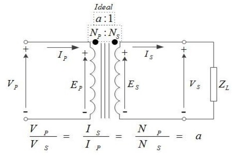
Why Short Circuit & Open Circuit Test are Required for a Transformer?
These two tests are performed on a transformer to determine:
- Equivalent circuit of transformer
- Voltage regulation of transformer
- Efficiency of transformer.
The power required for these Open Circuit test and Short Circuit test on transformer is equal to the power loss occurring in the electrical transformers.
Open Circuit Test of Transformer
Method 1:
No-Load Test of a Transformer:
- Connect the circuit as shown in figure below:
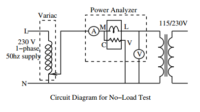
- Apply voltage to the LV side in steps upto the rated voltage and for each case record primary current and power drawn from the source. Also, observe the current waveform on the power analyzer.
- Increase the applied voltage by 10% and repeat the above step.
- Reduce the output voltage of the variac to zero and switch-off the supply.
Method 2:
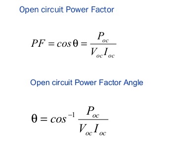
A voltmeter, wattmeter, and an ammeter are connected in LV side of the transformer as shown. The voltage at rated frequency is applied to that LV side with the help of a variac of variable ratio auto transformer. The HV side of the transformer is kept open. Now with help of variac applied voltage is slowly increase until the voltmeter gives reading equal to the rated voltage of the LV side. After reaching at rated LV side voltage, all three instruments reading (Voltmeter, Ammeter and Wattmeter readings) are recorded.
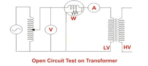
The ammeter reading gives the no load current Ie. As no load current Ie is quite small compared to rated current of the transformer, the voltage drops due to this electric current then can be taken as negligible. Since, voltmeter reading V can be considered equal to secondary induced voltage of the transformer. The input power during test is indicated by watt-meter reading. As the transformer is open circuited, there is no output hence the input power here consists of core losses in transformer and copper loss in transformer during no load condition. The no load current in the transformer is quite small compared to full load current so copper loss due to the small no load current can be neglected. Hence the watt meter reading can be taken as equal to core losses in transformer.
Let us consider wattmeter reading is Po.
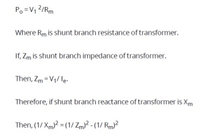
These values are referred to the LV side of transformer as because the test is conduced on LV side of transformer. These values could easily be referred to HV side by multiplying these values with square of transformation ratio. Therefore it is seen that the open circuit test on transformer is used to determine core losses in electrical transformers and parameters of shunt branch of the equivalent circuit of transformer.
Short Circuit Test of electrical transformers
Method 1
- Connect the circuit as shown in below figure:
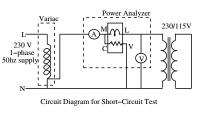
- Set the auto transformer output to zero. It is extremely important to note that a low voltage is to be applied to the primary winding.
- Adjust the output of the autotransformer such that rated current flows through the windings. Record the applied voltage, current and input power.
- Reduce the output voltage of the autotransformer to zero and put off the supply.
Method 2
A voltmeter, wattmeter, and an ammeter are connected in HV side of the transformer as shown in figure. The voltage at rated frequency is applied to that HV side with the help of a variac of variable ratio auto transformer. The LV side of the transformer is short circuited . Now with help of variac applied voltage is slowly increase until the ammeter gives reading equal to the rated current of the HV side. After reaching at rated current of HV side, all three instruments reading (Voltmeter, Ammeter and Watt-meter readings) are recorded. The ammeter reading gives the primary equivalent of full load current IL. As the voltage, applied for full load current in short circuit test on transformer, is quite small compared to rated primary voltage of the transformer, the core losses in transformer can be taken as negligible here.
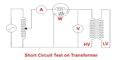
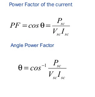
Let’s, voltmeter reading is Vsc . The input power during test is indicated by watt-meter reading. As the transformer is short circuited, there is no output hence the input power here consists of copper losses in transformer, since the applied voltage Vsc is short circuit voltage in the transformer and hence it is quite small compared to rated voltage so core loss due to the small applied voltage can be neglected. Hence the wattmeter reading can be taken as equal to copper losses in transformer.
Let us consider wattmeter reading is Psc .
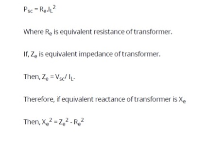
These values are referred to the HV side of transformer as because the test is conduced on HV side of transformer. These values could easily be referred to LV side by dividing these values with square of transformation ratio. Therefore it is seen that the Short Circuit test on transformer is used to determine copper loss in transformer at full load and parameters of approximate equivalent circuit of transformer.
Summary of This Article:
The open circuit test on transformer is used to determine core losses in transformer and parameters of shunt branch of the equivalent circuit of transformer. The Short Circuit test on transformer is used to determine copper loss in transformer at full load and parameters of approximate equivalent circuit of electrical transformers.
Credit 1, 2
Discover more from Electrical Engineering 123
Subscribe to get the latest posts sent to your email.

