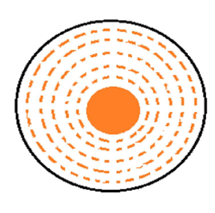
The distribution of current throughout cross section of a conductor is uniform only when DC is passing through it.
When Alternating Current(AC) is passing through a conductor, the current is non uniformly distributed over the cross section in a manner that the current density is higher at the surface of the conductor compared to the current density at its centre.
This effect is more as frequency of supply and size of the conductor is increased.
The phenomenon is called Skin effect.
It causes a larger power loss for a given rms AC than the power loss when the same value of DC is flowing through the conductor.
Hence, the effective conductor resistance is more for AC than for DC.
Why Skin Effect Occurs in Transmission Lines?
Consider the cross sectional view of the conductor during the flow of alternating current given in the diagram below.

Let us initially consider the solid conductor to be split up into a number of annular filaments spaced infinitely small distance apart, such that each filament carries an infinitely small fraction of the total current.
Let I be the total current. Let us consider the conductor to be split up into n filament carrying current ‘i’ such that I = ni .
Now during the flow of an alternating current, the current carrying filaments lying on the core has a flux linkage with the entire conductor cross section including the filaments of the surface as well as those in the core.
Whereas the flux set up by the outer filaments is restricted only to the surface itself and is unable to link with the inner filaments.
Thus the flux linkage of the conductor increases as we move closer towards the core and at the same rate increases the inductor as it has a direct proportionality relationship with flux linkage.
This results in a larger inductive reactance being induced into the core as compared to the outer sections of the conductor.
The high value of reactance in the inner section results in the current being distributed in an nonuniform manner and forcing the bulk of the current to flow through the outer surface or skin giving rise to the phenomena called skin effect in transmission lines.
Factors Affecting Skin Effect in Transmission Lines
The skin effect in an ac system depends on a number of factors like:-
- Shape of conductor.
- Type of material.
- Diameter of the conductors.
- Operational frequency
Proximity Effect:
Proximity effect in transmission lines indicates the effect in one conductor for other neighboring conductors.
When the alternating current is flowing through a conductor, alternating magnetic flux is generated surrounding the conductor.
This magnetic flux associates with the neighboring wires and generates a circulating current (it can be termed as ‘eddy current’ also).
The circulating current increases the resistance of the conductor and push away the flowing current through the conductor, which causes the crowding effect.
When the gaps between two wires are greater the proximity effect is less and it rises when the gap reduces.
The flux due to central conductor links with right side conductor.
In a two wire system more lines of flux link elements farther apart than the elements nearest to each other as shown above.
Therefore, the inductance of the elements farther apart is more as compared to the elements near to each other and hence the current density is less in the elements farther apart than the current density in the element near to each other.
As a result the effective resistance of the conductor is increased due to non uniform distribution of current.
This phenomenon is actually referred as proximity effect.
Proximity effect is pronounced in the case of cables where the distance between the conductors is small whereas proximity effect in transmission lines in the case of overhead system, with usual spacing is negligibly small.
Discover more from Electrical Engineering 123
Subscribe to get the latest posts sent to your email.

