Transformer is very simple and basic part of electrical system and considered most efficient of electrical components of machines. If we consider experimental models which are using superconducting windings then we may talk about achieving the the performance of 99.75 percent as well. In practice, energy is found to be lost in the windings, core and surrounding structures due to various causes as outlined below:
- Copper Losses in Winding resistance: Windings are made up of copper wire which get heated due to Joule heating when current flows through them. effect When working at higher frequencies, skin effect and proximity effect add to the losses due to winding resistance
- Eddy Current Losses: An eddy current is an electric current set up by an alternating magnetic field. These losses arise from the fact that the core itself is composed of conducting material, so that the voltage induced in it by the varying flux produces circulating currents in the material. Eddy current loss depends upon the rate of change of flux as well as the resistance of the path, it is reasonable to expect this loss to vary as the square of both the maximum flux density and frequency. If the core is solid and made up from ferromagnetic materials, it effectively acts as a single short-circuited turn. Induced eddy currents therefore circulate within the core in a plane normal to the flux, and cause resistive heating of the core material.
- Hysteresis Losses: During each A.C. cycle, current flowing in the forward and reverse directions magnetizes and demagnetizes the core alternatively. Energy is lost in each hysteresis cycle within the magnetic core. Energy loss is dependent on the properties (e.g. coersivity) of particular core material and is proportional to the area of the hysteresis loop (B-H curve).
- Magnetostriction Losses: The core undergoes minute physical expansion and contraction with the eachA.C. cycle due to the alternating magnetic field. This effect known as magnetostriction produces the familiar buzzing sound, and causes losses due to frictional heating in susceptible cores.
- Mechanical Losses: The alternating magnetic field causes fluctuations in the electromagnetic forces between the primary and secondary windings. These produce mechanical vibrations in nearby metal work and add to the buzzing noise.
- Stray Losses: All the magnetic field produced by the winding is not linked to the secondary winding due to the leakage of flux primary current It may induce eddy currents within nearby conductive objects, such as the transformer’s support and get converted to heat which is lost to the surroundings structure
- Power Loss due to the Cooling system: Cooling arrangement like cooling fans, is necessary generated in oil pumps or water-cooled heat exchangers for removing heat large power transformers. As the power consumption in the operation of the cooling system is unproductive, it is considered as power loss of the transformer.
Physical Explanation of Hysteresis Loss of Transformers
The magnetic core of transformer is made of ′Cold Rolled Grain Oriented Silicon Steel′. Steel is very good ferromagnetic material. This kind of materials are very sensitive to be magnetized. That means, whenever magnetic flux would pass through, it will behave like magnet. Ferromagnetic substances have numbers of domains in their structure. Domains are very small regions in the material structure, where all the dipoles are paralleled to same direction. In other words, the domains are like small permanent magnets situated randomly in the structure of substance. These domains are arranged inside the material structure in such a random manner, that net resultant magnetic field of the said material is zero. Whenever external magnetic field or mmf is applied to that substance, these randomly directed domains get arranged themselves in parallel to the axis of applied mmf. After removing this external mmf, maximum numbers of domains again come to random positions, but some of them still remain in their changed position. Because of these unchanged domains, the substance becomes slightly magnetized permanently. This magnetism is called “Spontaneous Magnetism“. To neutralize this magnetism, some opposite mmf is required to be applied. The magneto motive force or mmf applied in the transformer core is alternating. For every cycle due to this domain reversal, there will be extra work done. For this reason, there will be a consumption of electrical energy which is known as Hysteresis loss of transformer.

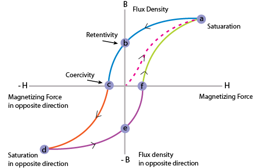
Hysteresis is the ‘lagging’ effect of flux density B whenever there are changes in the magnetic field strength H. When an initially unmagnetized ferromagnetic material is subjected to a varying magnetic field strength H, the flux density B produced in the material varies.
Hysteresis loss is associated with the phenomena of hysteresis and is an expression of the fact when ferromagnetic material is involved, not all the energy of the magnetic field is returned to the circuit when mmf is removed. It is known as hysteresis loss. The core of a transformer is subjected to an alternating magnetizing force and for each cycle of emf a hysteresis loop is traced out.
The lagging phenomenon of B behind H is called hysteresis. The tip of hysteresis loop can be joined to obtain the magnetization characteristics.
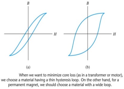
- Hysteresis loss results in a dissipation of energy which appears as a heating of the magnetic material. The energy loss associated with hysteresis is proportional to the area of the hysteresis loop.
- For AC-excited devices the hysteresis loop is repeated every cycle of alternating current. Thus a hysteresis loop with a large area is often unsuitable since the energy loss would be considerable.
- Silicon steel has a narrow hysteresis loop, and thus small hysteresis loss, and is suitable for transformer cores and rotating machine armatures.
Hysteresis Loop
A hysteresis loop shows the relationship between the induced magnetic flux density (B) and the magnetizing force (H). It is often referred to as the B-H loop.

The area of a hysteresis loop varies with the type of material. The area, and thus the energy loss, is much greater for hard materials than for soft materials.
- Hard material, which has a high remanence and a large coercivity.
- Soft steel, which has a large remanence and small coercivity.
- Ferrite, this being a ceramic-like magnetic substance made from oxides of iron, nickel, cobalt, magnesium, aluminium and mangenese; the hysteresis of ferrite is very small.
A disturbance in the alignment of the domains of a ferromagnetic material causes energy to be expended in taking it through a cycle of magnetization. This energy appears as heat in the specimen and is called the hysteresis loss.
Equation & Explanation of Hysteresis Loss in Transformer
Determination of Hysteresis Loss
 Consider a ring of ferromagnetic specimen of circumference L meter, cross – sectional area a m2 and N turns of insulated wire as shown in the picture beside, Let us consider, the current flowing through the coil is I amp, Magnetizing force,
  Let, the flux density at this instant is B, Therefore, total flux through the ring, Φ = BXa Wb As the current flowing through the solenoid is alternating, the flux produced in the iron ring is also alternating in nature, so the emf (e′) induced will be expressed as,


According to Lenz,s law this induced emf will oppose the flow of current, therefore, in order to maintain the current I in the coil, the source must supply an equal and opposite emf. Hence applied emf,

Energy consumed in short time dt, during which the flux density has changed,

Thus, total work done or energy consumed during one complete cycle of magnetism,

Now aL is the volume of the ring and H.dB is the area of elementary strip of B – H curve shown in the figure above,

Therefore, Energy consumed per cycle = volume of the ring X area of hysteresis loop.
Core Losses
The sum of hysteresis loss and eddy current losses is called core loss as both the losses occur within the core (magnetic material). For a given magnetic circuit with a core of ferromagnetic material, volume and thickness of the plates are constant and the total core loss can be expressed as follows. Core loss = Hysteresis loss + Eddy current loss It is rather easier to measure the core loss with the help of a wattmeter (W) by energizing the N turn coil from a sinusoidal voltage of known frequency.
Discover more from Electrical Engineering 123
Subscribe to get the latest posts sent to your email.


This was very helpful, Thanks a lot!