
The earthing system or earth electrode subsystem establishes the electrical connection between the building, structure or facility and earth.
This connection is necessary for lightning protection, useful in power fault protection, and and in the minimization of noise.
The earthing system should be tailored to reflect the characteristics of the site and the requirements of the facility. It must be properly installed and steps must be taken to assure that it continues to provide a low resistance connection throughout the life of the structure.
In order to achieve these objectives, it is mandatory:
- to first determine the electrical and physical properties of the site,
- design an earth electrode subsystem appropriate for the site,
- install the subsystem in accordance with the recommended procedures,
- and finally, measure the earth resistance of the subsystem to verify that it meets the recommended goals or design specifications.
Determination of Electrical Site Parameters (Site Survey)
Before beginning the design of an earthing system, conduct a survey of the site where the earth electrode subsystem is to be installed. Through this survey, determine the resistivity of the soil, identify significant geological features, gather information on architectural and landscape features which may influence the design of the subsystem, and review local climate effects.
This is best to conduct this earthing grounding survey in advance of the final site selection in order to avoid particularly troublesome locations.)
Soil Resistivity Test
As the first step of the site survey, measure the resistivity of the soil at several points over the area of the planned project site or facility. For even the smallest facility, the effective facility area in so far as the electrode subsystem is concerned is assumed to be at least 15 meters by 15 meters (50 feet by 50 feet).
For larger facilities, the facility areas are assumed to extend at least 6 meters (20 feet) beyond the basic building or structural outline, i.e. the ground floor plan, substation grid, tower footing, transformer housing, etc.
It is necessary that the soil resistivity be known over the area encircled or covered by the earth electrode subsystem.
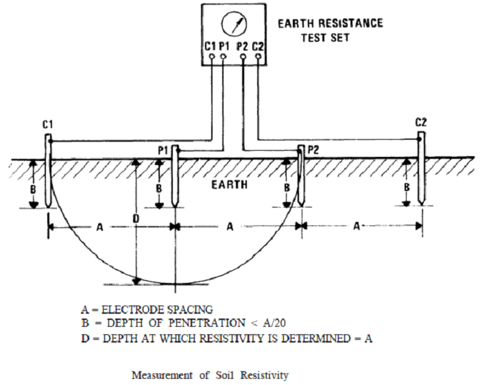
Step 1: A single soil resistivity measurement is made using the four-probe earth tester method in the following manner:
- At a location near the center of the site, insert the four short probes supplied with the earth resistance tester into the soil in a straight line as illustrated in below figure.
- A convenient probe spacing of 6 to 9 meters (20 to 30 feet) is recommended as a start. If probes are not supplied with the test set or if they have been lost or misplaced, four metal (steel, copper, or aluminum) rods, 1/4 to 3/8 inch in diameter and 12 to 18 inches in length, may be used.
- Drill and tap the appropriate screws, according to rod size i.e. 6-32, 8-32, or 10-24, and securely fasten the test set leads to the rods. Clamps may also be used for connecting the leads to the probes.
Step 2: Following the manufacturer’s instruction, obtain a resistance reading, R, with the earth tester set.
Step 3: Convert the probe spacing, A, to centimeters.
Step 4: Compute resistivity from p = 6.28 AR (in ohm-cm)
For example:
Assume that a resistance of 2 ohms is measured with probe spacing of 20 feet.
Convert 20 feet to centimeters: 20 ft x 30.5 cm/ft = 610 cm
Calculate resistivity p = 6.28 x 610 x 2 = 7662 ohm -cm
The earth resistivity reading obtained in above steps indicates the average resistivity of the soil in the immediate vicinity of the test area.
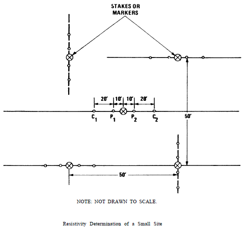
A resistivity profile of the site requires that the above procedure be repeated at many sample locations over the region being mapped. For small sites up to 2500 square feet (232 square meters), make at least one measurement at the center of the site and at each of the four corners of a 50-foot square as shown in below figure.
Drive a stake or marker at the locations shown. Position the potential and current probes in a straight line with the stake or marker centered between the probes.
Make a resistance measurement at each location and calculate the resistivity as in step above. Take the average of the five readings as the resistivity for the soil at the site.
If possible, soil measurements should be made during average/normal weather conditions. Measurements should never be made immediately after a rain or storm.
For larger sites, make measurements every 100 to 150 feet (30 to 45 meters) over the site area. Include in the site area the locations of support elements such as transformer banks, towers, engine-generator buildings, etc.
Choose a sufficient number of test points to give an indication of the relative uniformity of the soil composition throughout the area. Be particularly alert for the presence of localized areas of very high or very low resistivity soils.
Determine the Physical Properties of Site
Geological Effects
a. Identify the significant geological features of the site. Specifically, attempt to establish:
- the distribution of major soil types to include the locations of sand and gravel deposits,
- major rock formations,
- the presence of water sources to include underground streams, and
- the depth of the water table.
Utilize test boring, on site inspections, studies of local maps, and interview with local construction companies, well drillers, and other local personnel to obtain the desired information
b. Evaluate the information provided by these sources for indications of particularly troublesome (or particularly helpful) characteristics that may influence the design or installation of the earth electrode subsystem of the facility.
Physical Features Impacting Earthing System
Locate and identify those other physical features that will influence the general placement of the earth electrode subsystem, the location of test and access points, physical protection requirements, and the cost of materials and installation. For example, indicate on the general site plan:
- the planned physical layout of the building or structure,
- locations of paved roads and parking lots,
- drainage, both natural and man-made, and
- the location of buried metal objects such as pipes and tanks.
Local Climate Conditions
Review local climatic conditions and determine the annual amount and seasonal distribution of rainfall, the relative incidence of lightning, and the depth of freezing (frost line) typical of the area. Obtain the rainfall and frost line information from the local weather service; project the relative lightning incidences in the area.
Record the data and make it a part of the facility files for the site. Immediately, however, use this information to aid in the design of the earthing electrode subsystem for the facility to be constructed at the site.
Sharing is caring:

Discover more from Electrical Engineering 123
Subscribe to get the latest posts sent to your email.