
What is a wiring circuit and its components?
Two or more conductors (wires) through which a current flows from a source to one or more outlets. The source is where the electrical current originates within the house. Usually the breaker box or breaker panel.
A conductor is any type material used to carry electrical current. Which may also be called a wire.
Electrical Load is the total amount of electrical current required. Different types of circuits are needed to carry the load in each room. Wiring in each circuit is protected by an overcurrent device, either a fuse or breaker. If a circuit becomes overloaded, or a short circuit develops, the breaker will open to stop the current flow.
By providing several branch circuits within a house, it keeps costs down and allows for safe operation.
The load carrying capacity of a wire is measured in amperes and stated as ampacity. If the ampacity is exceeded, the wire will burn and melt.
Larger wire has a higher ampacity. Items that have higher electrical needs will require larger wire with a higher ampacity.
Types of Circuits
- Branch Circuits: A circuit that runs from a breaker to one or more outlets. Most circuits installed in homes are branch circuits.
- Feeder Circuits: A circuit between the breaker box and a sub-panel.
There are three types of wiring systems for distributing electrical power to consumers including light switch wiring.
- Single-phase two-wire system
-
Three-phase four-wire system
-
Three phase three wire system
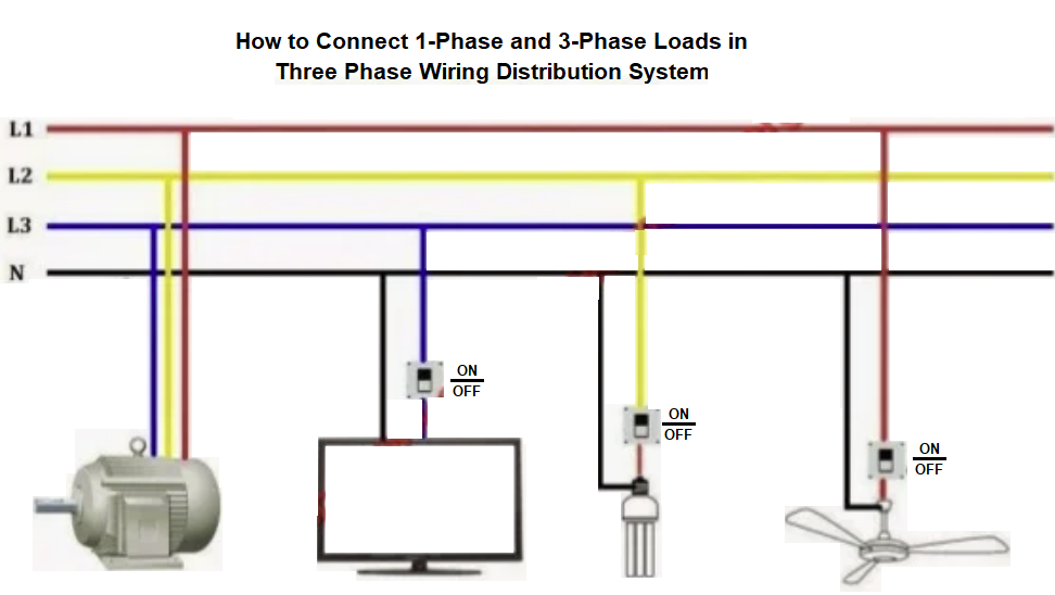
Single Phase Two Wire System (1-phase-2-Wire Domestic Wiring)
This home wiring system is common for domestic consumers, the most commonly used system is 1-phase 2-wire system (230V).
In this electrical wiring system power is often derived from a 400V, 3-phase 4-wire power distribution system.
Groups of consumers are connected between one phase line and the neutral conductor, thus providing 230V, 50Hz, 1-phase supply.
The consumers – groups are arranged such that the loads on the three phases remain balanced.
Three Phase Four Wire System ( 3-phase-4-wire Industrial Wiring)
For large industrial consumers, particularly those using heavy motor loads and drawing more than 1 MVA, the power is supplied from a three phase system at high voltage, such as 6.6kV, 11kV, or 33kV.
The consumer has its own substation to distribute power at appropriate voltages at different locations within his premises.
Three Phase Three Wire System (Transmission Wiring)
Because there’s no need to run a neutral wire for transmission service, and it saves on materials cost.
Four-wire systems are only useful where single phase loads are involved, really.
Transmission is always balanced three-phase(Delta).
So, using 3 wire system is economical and also results in lesser power loss.
Difference Between Neutral and Ground Wires
Neutral carries current equal to that carried by the phase wire.
Neutral is a circuit conductor that normally carries current back to the source (return path for the phase wire) and is connected to ground (earth) at the main electrical panel.
Ground is there for safety, and it should never carry current except when something has failed (it should only carry the leakage current). Even though both Neutral and Ground are attached to the same point inside the breaker box.
SWITCHES
Switch is an electromechanical device used to connect or disconnect a circuit and for controlling light switch wiring.
The moving part of a switch is used to connect or disconnect a circuit which is called a Pole.
Types of Switches
- Single Pole single throw switch.
-
Single pole double throw switch.
-
Double pole single throw switch.
-
Double pole double throw switch.
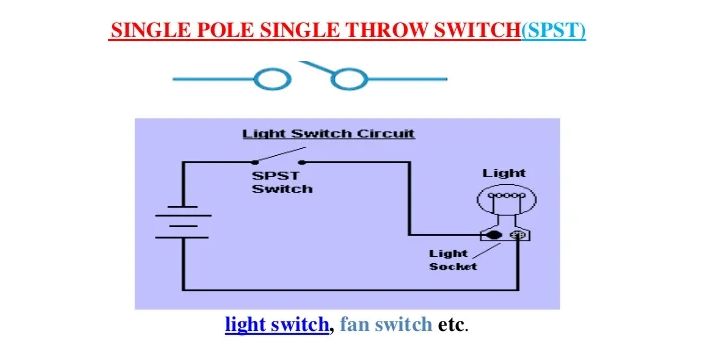
SINGLE POLE SINGLE THROW SWITCH (SPST)
This is a simple ON/OFF switch. It is also called as One Way Switch (in the US, they called it Two-Way Switch). Example: light switch, fan switch etc.
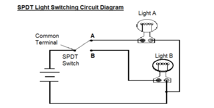
SINGLE POLE DOUBLE THROW SWITCH (SPDT)
A simple changeover switch: COM( Common) is connected to A or to B. This button has three pins in which, one pin is used as common and called a Two-Way Switch (in US, they called it Three- Way Switch). For example: SPDT switch is used to control two different circuits etc.
When the switch A is closed, then the current flows through the terminals, but only light A will glow and light B will OFF.
When the switch B is closed, then the current flows through the terminals and only light B will glow and light ‘A’ will OFF.
Here two circuits will be controlled through one source or one way.
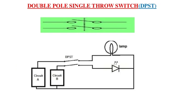
DOUBLE POLE SINGLE THROW SWITCH (DPST) / light switch wiring
A Double Pole Single Throw Switch has a lot of versatility being that it accepts 2 inputs, which makes it then be able to drives 2 different outputs in a circuit.
What it drives depends on the circuit design and what the circuit is intended to do. But DPST have enormous applications in circuits.
We can see from the circuit, how a DPST switch can be used to put a circuit in any of 1 of 2 modes.
When the switch is connected one way (circuit A), the lamp and LED will both be ON.
When connected the other way (circuit B), the lamp and the LED are both OFF.
So a DPST switch allows for control of 2 outputs (2 circuits), turning either both on or both off together.
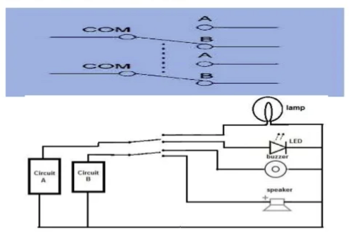
DOUBLE POLE DOUBLE THROW SWITCH (DPDT)
This switch is equal to two SPDT switches, it means two separate circuits, connecting two inputs of each circuit to one of two outputs.
Circuit A is connected to a lamp and an LED.
When is the switch is one way, the lamp is on and the LED is off.
When the switch is flipped the other way, the LED is on and the lamp is off.
Circuit B is connected to a buzzer and a speaker.
When the switch is one way, the buzzer is on and the speaker is off.
When the switch is flipped the other way, the speaker is on and the buzzer is off.
This shows the dynamic 2-mode capacity that DPDT switches allow, allowing control of 4 different devices.
Sharing is caring:

Discover more from Electrical Engineering 123
Subscribe to get the latest posts sent to your email.