
What is Circuit Breaker?
Electrical circuit breaker is a switching device which can be operated manually or automatically for controlling and protection of electrical power system respectively, it is a mechanical switching device, capable of making, carrying and breaking currents under normal circuit conditions.
Circuit breaker is also capable of making and carrying for a specified time and breaking currents under specified abnormal circuit conditions, such as those of a short circuit etc.
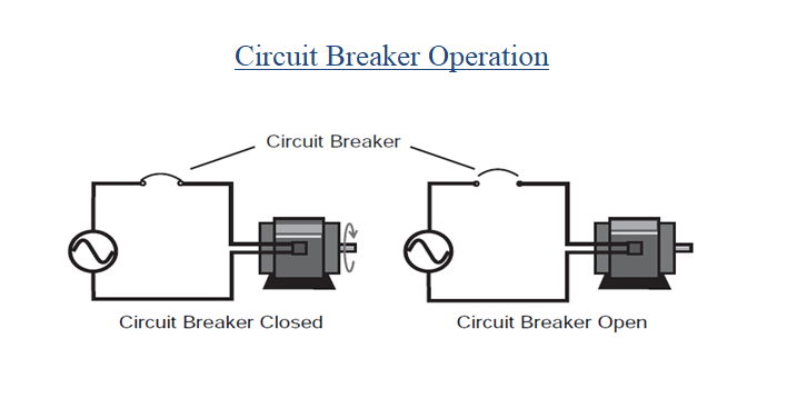
How Circuit Breaker Operates?
In the following illustration, an AC motor is connected through a circuit breaker to a voltage source.
When the circuit breaker is closed, a complete path for current exists between the voltage source and the motor allowing the motor to run, by opening the circuit breaker the path of current flow breaks and the motor stops.
The circuit breaker automatically opens when it senses faults in the circuit. After the fault has been cleared, the breaker can be closed, allowing the motor to operate.
Circuit Breakers Working Principle
The circuit breaker mainly consists of fixed contacts and moving contacts.
In normal “on” condition of circuit breaker, these two contacts are physically connected to each other due to applied mechanical pressure on the moving contacts.
There is an arrangement stored potential energy in the operating mechanism of circuit breaker which is realized if switching signal given to the breaker.
The potential energy can be stored in the circuit breaker by different ways like by deforming metal spring, by compressed air, or by hydraulic pressure.
But whatever the source of potential energy, it must be released during operation.
Release of potential energy makes sliding of the moving contact at extremely fast manner. All circuit breaker have operating coils (tripping coils and close coil), whenever these coils are energized by switching pulse, the plunger inside them displaces.
This operating coil plunger is typically attached to the operating mechanism of circuit breaker, as a result the mechanically stored potential energy in the breaker mechanism is released in forms of kinetic energy, which makes the moving contact to move as these moving contacts mechanically attached through a gear lever arrangement with the operating mechanism.
After a cycle of operation of circuit breaker the total stored energy is released and hence the potential energy again stored in the operating mechanism of circuit breaker by means of spring charging motor or air compressor or by any other means.
There are electrical characteristics of a circuit breaker which also should be considered in the discussion about circuit breaker operation.
The circuit breaker has to carry large rated fault power. Due to this large power there is always dangerously high arcing between moving contacts and fixed contact during operation of circuit breaker.
Arcing in circuit breaker can be quenching safely if the dielectric strength between the current carrying contacts of circuit breaker increases rapidly during every current zero crossing of the alternating current.
The dielectric strength of the media in between contacts can be increased in numbers of ways, like by compressing the ionized arcing media since compressing accelerates the deionization process of the media, by cooling the arcing media since cooling increase the resistance of arcing path or by replacing the ionized arcing media by fresh gasses.
Hence a numbers of arc quenching processes should be involved in operation of circuit breaker.
Circuit Breakers Types by Voltage Class
Low level circuit breakers
Circuit breakers having low voltage (less than 1KVAC) are common in domestic, commercial and industrial application, including:
Miniature Circuit Breaker MCB: Rated current not more than 100 A. Trip characteristics normally not adjustable. Thermal or thermal-magnetic operation. Breakers illustrated above are in this category.
Molded Case Circuit Breaker MCCB: Rated current up to 2500 A. Thermal or thermal-magnetic operation. Trip current may be adjustable in larger ratings.
Low voltage power circuit breakers can be mounted in multi-tiers in LV switchboards or switchgear cabinets.
The characteristics of LV circuit breakers are given by international standards such as IEC 947. These circuit breakers are often installed in draw-out enclosures that allow removal and interchange without dismantling the switchgear.
Large low-voltage molded case and power circuit breakers may have electrical motor operators, allowing them to be tripped (opened) and closed under remote control. These may form part of an automatic transfer switch system for standby power.
Low-voltage circuit breakers are also made for direct-current (DC) applications, for example DC supplied for subway lines.
Special breakers are required for direct current because the arc does not have a natural tendency to go out on each half cycle as for alternating current.
A direct current circuit breaker will have blow-out coils which generate a magnetic field that rapidly stretches the arc when interrupting direct current.
Magnetic Circuit Breaker
Magnetic circuit breakers use a solenoid (electromagnet) whose pulling force increases with the current.
Certain designs utilize electromagnetic forces in addition to those of the solenoid.
The circuit breaker contacts are held closed by a latch. As the current in the solenoid increases beyond the rating of the circuit breaker, the solenoid’s pull releases the latch which then allows the contacts to open by spring action.
Some types of magnetic breakers incorporate a hydraulic time delay feature using a viscous fluid.
The core is restrained by a spring until the current exceeds the breaker rating.
During an overload, the speed of the solenoid motion is restricted by the fluid.
The delay permits brief current surges beyond normal running current for motor starting, energizing equipment, etc.
Short circuit currents provide sufficient solenoid force to release the latch regardless of core position thus bypassing the delay feature.
Ambient temperature affects the time delay but does not affect the current rating of a magnetic breaker.
Thermal Magnetic Circuit Breaker
Thermal magnetic circuit breakers, are found in most distribution boards. These electric breakers incorporate both techniques with the electromagnet responding instantaneously to large surges in current (short circuits) and the bimetallic strip responding to less extreme but longer-term over-current conditions.
Common Trip Breakers
When supplying a branch circuit with more than one live conductor, each live conductor must be protected by a breaker pole.
To ensure that all live conductors are interrupted when any pole trips, a “common trip” breaker must be used.
These may either contain two or three tripping mechanisms within one case, or for small breakers, may externally tie the poles together via their operating handles.
Two pole common trip breakers are common on 120/240 volt systems where 240 volt loads (including major appliances or further distribution boards) span the two live wires.
Three-pole common trip breakers are typically used to supply three-phase electric power to large motors or further distribution boards.
Medium Level Circuit Breakers
Medium-voltage circuit breakers rated between (1 and 72 kV) may be assembled into metal-enclosed switchgear line ups for indoor use, or may be individual components installed outdoors in a substation.
Air-break circuit breakers replaced oil-filled units for indoor applications, but are now themselves being replaced by vacuum circuit breakers (up to about 35 kV).
Like the high voltage circuit breakers, these are also operated by current sensing protective relays operated through current transformers.
The characteristics of MV breakers are given by international standards such as IEC 62271. Medium-voltage circuit breakers nearly always use separate current sensors and protection relays, instead of relying on built-in thermal or magnetic overcurrent sensors.
Medium-voltage circuit breakers can be classified by the medium used to extinguish the arc:
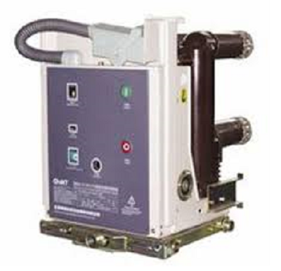
Vacuum circuit breaker: With rated current up to 3000 A, these breakers interrupt the current by creating and extinguishing the arc in a vacuum container.
These are generally applied for voltages up to about 35,000 V, which corresponds roughly to the medium-voltage range of power systems.
Vacuum circuit breakers tend to have longer life expectancies between overhaul than do air circuit breakers.
Air circuit breaker: Rated current up to 10,000 A.
Trip characteristics are often fully adjustable including configurable trip thresholds and delays.
Usually electronically controlled, though some models are microprocessor controlled via an integral electronic trip unit.
Often used for main power distribution in large industrial plant, where the breakers are arranged in draw-out enclosures for ease of maintenance.
SF6 circuit breakers extinguish the arc in a chamber filled with sulfur hexafluoride gas.
Medium-voltage circuit breakers may be connected into the circuit by bolted connections to bus bars or wires, especially in outdoor switchyards.
Medium-voltage circuit breakers in switchgear lineups are often built with draw-out construction, allowing the breaker to be removed without disturbing the power circuit connections, using a motor-operated or hand-cranked mechanism to separate the breaker from its enclosure.
High Level Circuit Breakers
Electrical power transmission networks are protected and controlled by high-voltage electric breakers.
The definition of high voltage varies but in power transmission work is usually thought to be 72.5 kV or higher, High-voltage breakers are nearly always solenoid-operated, with current sensing protective relays operated through current transformers.
In substations the protection relay scheme can be complex, protecting equipment and busses from various types of overload or ground/earth fault.
High-voltage breakers are broadly classified by the medium used to extinguish the arc.
- Bulk oil
- Minimum oil
- Air blast
- Vacuum
- SF6
Circuit breakers can be classified as live tank, where the enclosure that contains the breaking mechanism is at line potential, or dead tank with the enclosure at earth potential.
High-voltage AC circuit breakers are routinely available with ratings up to 765 kV. 1200KV breakers are likely to come into market very soon.
High voltage circuit breakers used on transmission systems may be arranged to allow a single pole of a three-phase line to trip, instead of tripping all three poles; for some classes of faults this improves the system stability and availability.
Short Circuit Capability of Circuit Breaker
The switching capacity is the r.m.s value of a current which a switchgear or a fuse can still shut-off under specified conditions in an operationally safe way.
Both the short-circuit making capacity and short-circuit breaking capacity of circuit breakers must be larger than or equal the short-circuit current at the place of installation.
Rated short-circuit breaking capacity ICU and ICS
ICU is the maximum breaking capacity of a circuit breaker, it is expressed in kA and must be as large as the prospective short-circuit current at the site of installation.
Circuit breakers that have switched-off at the level of the ultimate short-circuit breaking capacity, are reduced service able afterwards and should at least be checked regarding functionality.
There may be changes in the overload trip characteristic and increased temperature rise due to the erosion of contact material.
Rated service short-circuit interrupting capacity ICS
ICS values are usually lower than the values for ICU.
Circuit breakers that have been switching-off at the level of the service short-circuit breaking capacity continue to be serviceable afterward.
In plants in which interruptions to operations must be kept as short as possible, product selection should be carried out based on ICS.
Circuit breaker Breaking time
Breaking time varies between (80-120) ms for circuit breakers up to 12kv, (40-80) ms for circuit breakers above 36kv, it is less than 60 ms for circuit breakers 145kv, and less than 50 ms for circuit breakers 420kv.
Fault clearing Time
- Fault clearing time=relay time + circuit breaker time
- Relay time= instant of fault to closure of trip circuit
- Circuit breaker time = opening time + arcing time
Mechanism of circuit breaker Operation
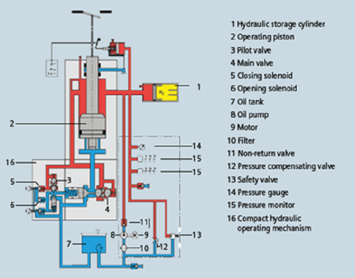
Hydraulic mechanism CB uses oil pressure to contact and discontact the main contacts of circuit breaker.
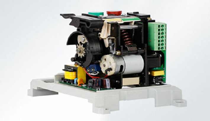
Motor wound spring circuit breaker uses motor force to charge the spring to disconnect the circuit when receiving trip signal.
Pneumatic circuit breaker mechanism
DC Type Circuit Breaker
The DC circuit breaker topologies may be divided into three main types.
Resonance DC breakers
Solid state DC breakers
Hybrid DC breakers
Resonance DC Circuit Breakers
Attempts to develop resonance HVDC circuit breakers were made as early in the 1980s’. The topology consist of mechanical switches and interrupts the current when a zero crossing is generated with the help of a capacitive inductive current path (commutation current path) in parallel with the main mechanical switch.
The topology also includes an absorbing branch consisting of MOVs. The technology has been proven too slow for fault current interruption in DC grid based on VSC technology.
The resonance topology may still provide useful applications such as load switching as it has a low resistive on-state loss compared to newer topologies.
The main branches of the resonance DC breaker topology are:
- nominal current path
- current commutation path
- energy absorption/dissipation path
Under normal operation the current is flowing through the nominal current path. If the breaker receives an interruption command, the mechanical switch will open and arc will occur and current will start to commutate into the commutation path.
At this stage, the current oscillations are generated. The voltage drop of the arc contributes to generate current oscillations due to the commutation path which will provide the zero current crossing and eventually extinguish the arc.
Thereafter, the current will flow into absorption path in order to dissipate the residual magnetic energy in the system.
Solid State DC Circuit Breakers
The solid state topology consists of semiconductor devices such as the insulated gate bipolar transistor (IGBT) or gate turn-off thyristor (GTO) and parallel MOVs.
Under normal operation the current flows through the devices. To interrupt the current, the devices are switched
off and current is commutated into the parallel MOV which here function both as the commutation path and the energy absorbing path.
Similar to the resonance topology, the MOV will dissipate the energy stored in the system.
Bi-directional current interruption is achieved by placing a similar IGBT with an anti-parallel diode in anti-series. More breaker cells may be placed in series to increase the rated voltage level.
The solid state state circuit breaker has proven to break current with the required speed for fault current interruption.
But as the semiconductors are conducting current under normal operating conditions, the losses due to the voltage drop over the breaker will be high especially in high voltage applications.
Hybrid DC Circuit Breakers
Hybrid topologies consists of both mechanical switches and semiconductor devises.
ABB and ALSTOM have developed HVDC circuit breaker prototypes which are presented as promising technologies in recent research literature.
The breaker may be seen as an extension of an IGBT based solid state topology, since the breaker essentially has an additional branch with a mechanical low-ohmic ultra fast disconnector (UFD) and a load commutation switch (LCS).
The LCS is also a solid state DC breaker, but has only sufficient breaker cells in order to commutate the current into the main breaker.
The hybrid topology overcomes the issue with conduction losses of the solid state topology by letting nominal current under normal operation flow through a nominal current path consisting of the LCS, and a UFD.
When the circuit breaker receives an interruption command, the LCS switches off and commutates the current into the main breaker similar to the solid state breaker.
After the commutation, the UFD opens and creates a physical isolation, protecting the LCS from the voltage drop when the main breaker interrupts current.
The UFD is a key component to keep the losses under normal operation as low as possible and obtaining the fast current interruption needed.
UFD is an electromagnetic actuator, using magnetic forces in order to obtain the fast switching speed required.
Sharing is caring:

Discover more from Electrical Engineering 123
Subscribe to get the latest posts sent to your email.