
Horizontal Directional Drilling is a guided horizontal boring system capable of installing utilities such as steel pipes and underground cables.
Its primary application is in developed areas where surface disruption is a serious consideration, not only because of cost but also because of smooth traffic flow, customer satisfaction and environmental friendly.
The horizontal drilling technology is totally safe and tremor free. It will not result in disturbances to surrounding environments and soil composition.
Directional drilling is unobtrusive to community in terms of noise level and traffic disruptions. When used in congested and high traffic areas, this method causes the least disturbance. This technique can be applied to drill through the river, road, housing area, railway track and airport runway etc.
What is Horizontal Drilling Technology
The equipment can produce tunnels ranging in size from 50 mm to 500 mm with typical run lengths of between 120 m to 360 m depending on soil conditions, equipment used and drilling depth.
Horizontal drilling technology uses high-pressure fluid jets for cutting the ground. These jets are sometimes augmented with carbide cutting blades to help penetrate the more consolidated sediments and permit operation in chalk, some shale, and occasional encounters with rubble and gravel up to 30 % in volume.
The drilling fluid is a mixture of water and bentonite. Fluid jet cutting with bentonite provides a means of excavating sediment while at the same time leaving a lubricated tunnel for installing the utility.
Bentonite solution is a viscous fluid that suspends the sediment particles and transports them back to the surface. Fluid jets will cut the sediment but will not cut into adjacent utilities whether they be concrete, metal or plastic.
Operating pressure for the fluid jets are typically up to 250 bar and jet diameters are typically 1 mm or less.
With the cutting head and back-reamer arrangement used, the maximum fluid consumption is 30 liters per minute when producing tunnels up to 175 mm.
The fluid jets at 250 bar penetrate about 1 cm into clay type sediments. This means that high pressure fluid jet cutting is substantially different from water boring techniques, which uses much larger quantities of fluids that can cause substantial voids and result in surface subsidence.
The system uses the orientation of the jets and head shape to control the path of the boring or drilling tool.
A separate piece of equipment above the ground, in combination with a transmitter located in the boring or drilling head, determines the position of the tool to within 2.5 cm at typical placement depths of about 1.5 m.
Tunnel placement accuracy can be held to 15 cm depending on the requirements of the job and the sediment type. A contoured path requiring a tool steering radius of 9 m or more can be maintained with equipment.
With the placement accuracy capability, guided boring system can be used in the vicinity of other utilities after first locating the existing utilities in the ground either electronically of by means of small excavation pits. Once the utilities are exposed, a course can then be carefully laid out to avoid running into existing utilities.
Since no trenching is involved, the course can be above, under or to the side of the existing utilities, allowing much more flexibility in placement of the new utility.
Unlike trenching, there is generally no difficulty in going deeper to get under a sewer, water pipe or other utilities. The depth of the tool can be accurately measured down to 25 m with the electronic locating equipment.
Because of the accurate placement capability, many utility companies will allow drilling next to active primary electric cables, while contractors using conventional techniques have to de-energize the cables, which contributes to further customer disruption.
Horizontal Directional Drilling Process
The entire drilling process is controlled by an operator from the central control panel of the mobile power supply unit together with one other operator at the site, who remotely directs the drill head with the help of a specialized receiver.
The mobile supply unit as well as hydraulic power produces all power necessary for the drilling process.
A radio-detection unit is used to investigate and locate any hidden obstacles such as undetected pipes or other cables along the proposed drill path.
The field power unit provides the high-pressure cutting fluid, hydraulic, pneumatic and electric connection.
Once these pits have been dug, the drill unit is brought to the site.
The unit is set up 4m to 5 m behind the first access pit.
Tool and the first 3 m section of drill pipe are put on the drill frame, which is angled at about 15 degrees to the ground.
The directional drilling or guided boring process begins by drilling into undisturbed surface at the 15 degrees angle. As the tool penetrates the ground, the second drill pipe is added. The process continues with the steering controlled so that the drilling tool will enter the first pit level at the proper depth.
The success of horizontal directional drilling lies on the construction of the drill head and reamers.
The drilling process can be divided into two main working procedures.
Stage 1: Firstly, a small entrance called the ‘start pit’ is dug at the convenient location. Then the drilling tool is attached to the drill rods and advanced through the ground to reach a target pit where the utilities cable or pipes are to be pulled.
Bentonite is emitted from jets into the drill tool and forced through the ground forming a pilot hole. The diameter of mud pressure and mudflow transports the removed soil back along the pilot hole to the start pit.
A transmitter is located in the drill head allowing the operator to locate the drill head to a tolerance of 2 cm.
With a two ways radio, the operator is able to issue command in steering the drill head along the desired drill run, thus giving total control.
The drill head can be steered in a straight line or in any other selected direction to the left, right, up or down. The drilling machine can drill up to length of 1800 m depending on soil conditions.
Stage 2: Involves back-reaming and product pipes installation which in other words, ‘the return journey’. Upon reaching the target pit, the drill head is then removed from the drill rods in the target pit. A back-reamer relevant to the size of the utility cable to be installed is then attached directly behind the reamer.
The back-reamer has a series of jets, which produce sufficient mudflow and pressure to cut away and remove soil, widening the pilot hole to the desired diameter. Cable or duct diameter may range from 50 mm to 500 mm. The drill rods will continue to rotate and retract, pulled along the utility cable, attached and the product is simultaneously installed, stress free.
How this Drilling Technique Works
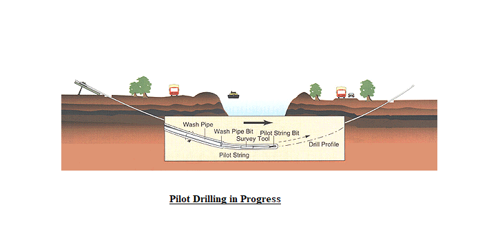
The directional drilling or guided boring system techniques is generally divided into three phases.
Phase 1: The key to success is the accuracy of the initial pilot tunnel, the steering tool is guided along the pilot tunnel enabling the crossing to be carried out exactly as planned.
The steering tool appears in the correct position required on the other side of the road, river or target pit.
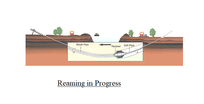
Phase 2: A wash-pipe is then fitted over the pilot string and advanced whilst rotating.
When a wash appears on the opposite side or target pit, the pilot string is retracted.
The wash-pipe is then fitted with a reamer and pulled back to the starting point on the other side.
This process widens the initial pilot tunnel, if further widening is required this process is repeated.
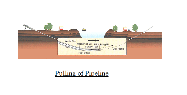
Phase 3: The product pipes to be installed is in position ready to be attached to a swivel, which is then attached to the reamer.
The reamer is then retracted with rotation and mud, and the customer’s product is installed rotation free on this final crossing.
The drilling mud protects the product and lubricates the installation process.
Health & Safety Requirements
During the entire drilling and back-reaming operation, the safety equipment and procedures will protect the operators from any possible injury caused by inadvertent contact with the energized electric cables underground.
Although this rarely occurs, the safety equipment and procedures ensure that operators are protected from electrical hazards.
Because of the safety equipment and procedures, most utility companies will allow drilling operations next to their live cables, while contractors using surface trenching and unguided boring techniques are required to disconnect power in the vicinity of the installation.
This means that new electric cable can be installed adjacent to the failing electric cables through out an entire city section with only a brief disruption to customers when switching over from the old cable system to the new cable system.
Similar benefits can also be experienced with the installation of telecommunication cables and gas pipes in common trenches with electric utilities.
Sharing is caring:

Discover more from Electrical Engineering 123
Subscribe to get the latest posts sent to your email.