
The purpose of this electrical method statement is to describe the methodology which contractor is adopting during the execution of the cable installation work.
Further following this method will ensure that work is done in controlled and safe manner as per project scope complying with specifications, Standards and procedures.
The scope of this electrical work procedure covers the cable laying pulling installation and termination of power, instrumentation and earthing cables for the project.
Roles & responsibilities:
Construction Manager and electrical project engineer will be responsible for all the activities.
Surveyor will be responsible for the setting out as well as the elevations.
Safety Officers and Site Supervisors will be responsible for all the related activities and the personnel working at site.
QA/QC will ensure the implementation of project quality plan requirements.
Health, Safety and Environmental Requirements
Temporary barricades shall be provided around the working area prior to commencement of site work.
Safety signboards, warning tape and signs, cones shall be provided around the working area confirming the safety of personnel and assets.
Tool box meetings shall be conducted every week and the reports shall be submitted.
The construction area shall be neat and tidy at all times and all unwanted materials / debris shall be transported to approved dumping site on daily basis.
Tools & Equipment’s
Arrange below tools and equipment before start of work:
- Hydraulic jack / cable jack
- Rollers
- Compactor
- Shovel
- Trucks
- Cable Reel Stand
- Puller Machine
- End Tying Basket
- Megger (0 – 5 KV)
- Continuity Tester
Cable Laying General Requirements
Cable Installation shall comply with reference codes and design documents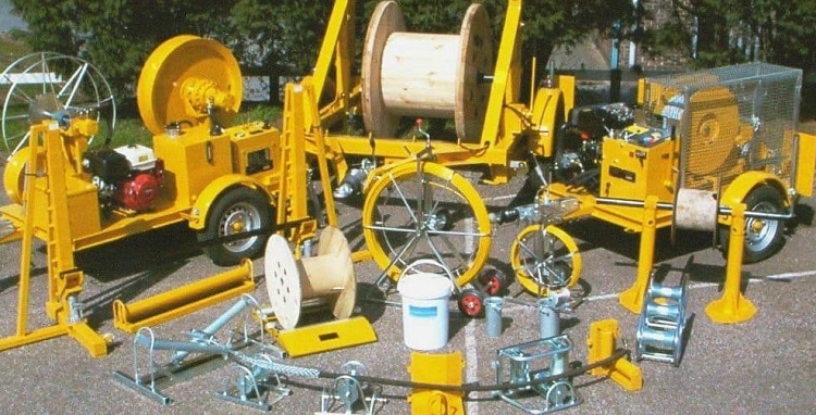
All cable drums shall be checked with packing lists and confirmation of mechanical damage will be done.
During cable drum shifting; check mechanical damage, nameplate with cable schedule and drum list and phase rotation of the cable.
Assure necessary PPE ,tools and equipment for cable pulling. Check the latest cable drum list and cable schedule. Check if all cable supports are installed and fixed.
All wires and cables shall be megaohm meter tested
Cables to be buried or used externally will be steel wire armored.
Cables will be directly buries, laid in concrete trenches, fastened to cable trays rack, or in underground ducts
Check for the following:
Proper type, size, color and number of the wires and cables are being installed
For long pulls the pull is performed as per required pulling tension
Cable is not pulled around too many bends and the radius is not too tight.
Ambient temperature is as per required by cable manufacturer
Proper pulling compound is used
Wires/Cables are protected from mechanical damage during pulling
Cable fill is as per the required standards
Minimum curve radius for cables, where D is the overall diameter of the cable, shall be 6D for un-armoured cable and 8D for armoured cable.
Junctions/slices where not removable, shall be made using sleeves, crimped or welded, restoring the integrity of the line by appropriate heat shrinkable sleeves.
Cable splicing shall be prohibited except in the case of cable length exceeding the supplied lengths
Cable Pulling Method Statement Works
Direct buried cables shall be taken to ensure that the laying area is not subject to landslide or cracking, that there are no obstacles in the subsoil and there is no soil contamination.
The bottom of the trench shall be backfilled with a layer of fine sand as per the drawings. The fill material shall be tamped and any hard material which could damage the cable will be removed.
Install cables on layer of the cleaned and tamped sand. Ensure to avoid excessive force and twisting of cables.
Cut the cables from the drums as per the actual cable length in accordance to the drum schedule and drum allocation sheets.
Cable drums shall be rotated in direction of the arrow.
Check Drum jacks provided are suitable for the cable drum loads.
Maintain proper spacing between the cables.
Provide protection to the cables at crossings with pipes, civil works to prevent mechanical damage.
Both ends of the cable to be firmly sealed with tape to prevent entry of water.
Intermediate cable markers to be firmly attached to the cables.
Control cables will be laid along the LV cables.
HV cables to be laid in separate trays.
Arrange the cables properly to minimize crossovers and twists.
All cables will be secured to the trays by using the nylon fasteners.
Cables leaving the trays will be properly protected by pipes/channels.
All buried cables to be secured by covering with sand, tiles, warning tapes at specified depths.
Marking of Cables
All cables will be marked as per cable schedule.
Buried cables will be tagged with corrosion resistant tags.
Cable marking shall be positioned properly to read and identify.
Cable Termination and Connection work
High voltage cable termination work will be done by certified cable terminator.
The cable to be checked as per the before cable termination work.
Cable bends in the terminal boxes shall be big as possible.
If cable glands are used cables will be checked before the work starts.
Cable core markers to be firmly attached.
Before termination, insulation resistance check will be done. Interphase continuity check will also be done.
Pressure and compression terminals to be used, which shall be of correct size for the cable.
Terminals shall be connected.
Cable arrangement after the termination shall be neat and tidy.
After completion of termination, insulation resistance check will be done. Interphase continuity check will also be done.
Cable Testing and Records
Insulation resistance test will be carried out by using approved and calibrated equipment.
Testing will be witnessed by QA/QC person
DC high voltage test will be conducted after confirming the cables are properly laid as per schedule and specifications.
| Voltage Class | Test instrument | Acceptance Value |
| M/V Cable | 5000 VDC | >100 Mega ohm |
| L/V Cable | 1000 VDC | >20 Mega ohm |
| Control, Instrumentation, Communication cable | 250 VDC | >1 Mega ohm |
Attachments
Job Safety Analysis
Field Installation Check List
Termination Inspection Check list
Insulation and continuity test for LV Cable
Insulation and continuity test for Instrumentation/Communication Cable
Sharing is caring:

Discover more from Electrical Engineering 123
Subscribe to get the latest posts sent to your email.