
The purpose of this document is to detail the testing & commissioning procedures of the Building Management System BMS.
Below is list of some necessary tools & instruments. Calibration certificates of the testing equipment will be produced during testing and commissioning.
- Laptop with Ethernet cross cable
- Multi-meter. (A valid test/calibration certificate will be available for inspection)
- General toolbox comprising screw-drivers, pliers, etc.
All above equipment, tools, & safety wear shall be suitably sized and designed to meet the project’s specifications, and shall be of good and safe, working order within acceptable parameters of applicable Environment Health & Safety Management System.
Some of the basic installation specifications include:
- Twisted-pair simple bus cable shall link maximum of 64 number of controllers (Alerton BACtalk VLCs other manufactures unitary controllers) to the Global Controller through the MS/TP network.
- MS/TP uses the EIA485 signalling standard on twisted-pair cabling in a simple bus (Daisy-Chain) configuration.
- The bus cable shall be a 22AWG, tinned copper, shielded twisted pair (STP) wire, lower capacitance cable and shall be capable of handling information exchange.
- All the Global Controllers will be connected to 10Base-T or 100Base-TX dedicated building services network through Integrated Ethernet Adapter Circuitry with RJ-45jack
- Power supply for sensors and actuators will be taken from the DDC panel.
Pre–commissioning Procedure for Building Management System BMS
Conduct a visual inspection to ensure that all DDC panels, sensors, actuators and other system devices are installed as per the approved points list, schematic drawings and specifications.
Check that the wiring of field devices with DDC panel is correct & complete.
Set the MAC address in Controller using DIP switch.
Supply power to the DDC controller.
Connect the DDC controllers to the BMS PC through the MSTP network. Assign software addresses to the DDC controllers.
Save the DDC controllers & their properties to the BMS PC (Database)
Check all field devices inspections are approved and copy attached with commissioning documentation file.
Check the calibration certificate of all measuring and testing instruments for validity.
BMS Testing & Commissioning Sequence & Procedure
Fan Coil Unit FCU Commissioning
General: Unit will be installed in the space without ducting. Each fan coil unit consists of three speed fan and chilled water cooling coil with two way modulating valve. The DDC controller will be mounted next to the unit. Three speed fan and valve actuator will be wired from this controller. Also the room thermostat will be wired to DDC controller.
Fan control: The start/stop of three speed supply fan will be based on the speed selection from room thermostat and also this fan control can be overridden from BMS for auto operation.
Temperature control: Under normal condition, based on space temperature, the DDC controller will modulate the cooling valve to achieve desired temperature set point. This temperature set point can be adjusted from the BMS.
Commissioning Procedure:
- Configure the input/output settings in the DDC program.
- Down load the DDC program to the DDC
- Verify supply and return air temperature readings between sensors and BMS graphics and record in the test report.
- Override the three speeds through BMS graphics. Verify the actual speed changes with fan itself and status indication in BMS graphics.
- Confirm the correct operation (Open/Close) of valve actuator with respect to the temperature set point changes.
- Complete Testing and Commissioning report.
Air Handling Unit AHU Commissioning
General Requirements
The system consists of a filter section, chilled water cooling coils with Pressure independent control valve, supply fan with VSD, associated Relief fan with VSD, modulating outside air I return Air dampers, ON/OFF Relief Air dampers, combination space temperature/humidity.
Sensors and thermal dispersion air flow measuring stations.
- Run status via a differential pressure switch mounted across the fan.
- Fresh & Return air damper Modulating control & feedback
- Return air damper open close Command & Status.
Chilled water cooling with 2-way modulating valve controlled by BMS according to the cooling demand.
Filter section status will be monitored by BMS through air differential pressure transmitter across the following filters.
Pre & Bag filter: If pressure exceeds predetermined set point then dirty alarm will be established by controller.
Sensors will be mounted:
- Supply, Space & Return air duct Temperature/ Humidity
- Supply & Return Pressure
- Supply Smoke Detector
- Cooling coil Immersion Temperature (Supply & return)
Fire alarm signal will be connected to starter panel to switch off the fan in case of fire.
AHU Start- Up and Fan Operation
The unit can be started and stopped locally through the HOA switch on the starter panel.
When this switch is in AUTO, the fan can be started and stopped remotely through the BMS, provided the following conditions are met:
- The motor starter is not in Trip state.
- There is no extant (un-reset) air-flow failure alarm.
- Fresh-Return Dampers are open.
Once supply fan has started, the differential pressure switch installed across the supply fan will verify the run status of the supply fan and enable the temperature control.
Return fan will start independently and the differential Pressure switch across the Return fan will verify the run status of Return fan.
Dampers Position: Fresh & Return Air Dampers will be maintained at full Open position.
Temperature Control
When the unit is OFF, the two way cooling valve will be fully closed. After airflow is established, which is confirmed by closing of the airflow switch, the temperature control will be enabled.
A PI control loop is used to generate a Space Temperature Control Signal which is then used to modulate the cooling valve as required to maintain the Space Air Temperature at the Set point (adjustable from BMS graphics).
Under normal conditions, on a demand for cooling which is based on Space air temperature with respect to temperature set point, the cooling valve will modulate to open. Valve Once the required temperature is achieved the cooling valve starts to modulate to closed.
Relief Fan Operation: Depending up on Differential Air flow via Air flow stations Space Positive pressurization maintained by VFD. If there is Positive differential Flow rather than return VFD will maintain same state to match Set point otherwise VFD Speed increased gradually to get Set point.
Static Pressure Control: Depending upon Static pressure set point present pressure will be matched with set point by ramping down and ramping up VFD speed.
Shutdown Operation: The following actions occur during the shutdown sequence:
- Chilled water valve is commanded to close.
- Supply fan is switched OFF.
- Return fan is switched OFF.
- Fresh air damper is closed (100 %.)
- Exhaust & Return air dampers are closed (100 %.)
Fan Alarm condition
Fan run status will be monitored by the BMS through a differential switch installed across the fan, if no air flow is sensed by the differential pressure switch while the fan is commanded to run by BMS, a failure alarm will be generated after a time delay (adjustable). The following happens when an alarm occurs:
- The alarm will be displayed in the BMS graphics.
- A pop-up window will appear with a description of the alarm. Alarm will be printed.
- The unit will be automatically shutdown.
- The cooling valve will be commanded to fully closed position.
After fault rectification, the alarm point has to be reset at the BMS/HOA before the unit can be brought back into automatic operation.
Fire/smoke Alarm condition
Smoke Detector on Supply Duct shall stop the fans in case of smoke on duct. Upon receipt of a Fire Alarm signal, Return & Relief Dampers shall be opened fully and Relief Fan shall be on at the same time Fresh Air Dampers shall be closed as well as Supply fan shall be off.
The Supply fan motor is turned OFF by a hardwired link between the Fire Control Panel and the starter control panel).
When the Fire Alarm has been reset, the unit will return by resetting HOA/BMS operation.
Commissioning Steps
Configure the input/output settings in the DDC program.
Download the DDC program to the DDC controller.
Verify the readings for all inputs between the field and BMS graphics and record in the test report.
Activate outputs such as fan control and cooling valve from BMS Graphics and verify the actual operation in the field.
Confirm the operation of modulating valve with respect to temperature set point.
Observe and verify the start-up and shutdown sequence of the unit with BMS mentioned above
Check the sequence o.f operation of AHU during normal condition.
Check and verify the shutdowns, including fire condition.
Perform the functional tests, which include airflow fail, alarm reset and manual·override.
Complete Testing and Commissioning report.
BMS Commissioning of Chilled Water System
Sequence of Operation Chilled Water Pump Lead/Lag/Standby Selection
- Provide a lead/lag/standby manual command on the chilled water system graphical display for each chilled water pump.
- Lead selection shall allow the BAS to start the pump and modulate speed to maintain the differential pressure set
- Lag selection shall allow the BAS to enable the pump when the lead pump is near full capacity.
- Standby selection shall allow the BAS to start the pump when the lead or lag pump shows a run status failure alarm or VSD fault alarm
- Display run time total hours for each pump. The BAS shall automatically rotate the lead, lag, and standby pumps every week (adj.). Provide the option to manually switch the lead, lag, and standby pump status from the OWS.
Heat Exchanger Sequence of Operation
Depending up on Heat exchanger Outlet Temp (secondary side), Set Point (5.8 C, adj.),
Lead Heat Exchanger Isolation Valve Opens (secondary side)
Primary side Modulating valve will be modulated up to 100%. If there is further demand then second Exchanger Isolation valve opens and Modulating valve will modulate up to 50%
and lead Exchanger modulating Valve will be modulated at 50% simultaneously.
If there is further command then Both Modulating valves will be modulated at 100%.
If there is further demand then third Exchanger Isolation valve opens and Modulating valve will modulate up to 50% and other Exchangers modulating Valve will be modulated at 50% simultaneously.
If there is further command then three Modulating valves will be modulated at 100%.
If there is no demand then reverse order of sequence which mentioned above will be occurred.
Chilled Water Differential Pressure Control
The BAS shall use the differential pressure sensor that has a reading furthest below set point for control of the chilled water pump(s).
The chilled water differential pressure sensor shall modulate the speed of the enabled chilled water pump(s) to maintain a chilled water system differential pressure set point of 1 bar (adj).
The actual set point shall be field determined by balancer and programmed by BAS contractor.
Chilled Water Pumps Staging Control
a. Upon chilled water system enable, the lead pump shall be enabled upon confirmation of the lead heat exchanger isolation valve open status.
b. The heat exchanger shall operate as described above to maintain the system differential pressure.
c. If the lead pump VSD remains above 70% speed (adj.) For an adjustable time period (15 minutes, adj.) The lag pump shall be enabled.
d. The lead pump VSD speed shall be reduced to 35% and the lag pump VSD shall be increased to 3.5%.
e. After an adjustable time period (5 minutes, adj.) both pumps shall operate at the same speed control signal and shall ramp up and down in unison to maintain the pressure set point.
f. If both pumps VSD speed drops below 30% for an adjustable time period (15 minutes, adj.), the lag pump shall be disabled.
g. The standby pump shall be enabled upon failure of either the lead or lag pump.
BMS Monitoring of Chilled Water Pumps
In addition to the input points mentioned in the above sequence of operation, the following points are also monitored by the BMS.
- Pump H-0-A switch status
-
Pump trip alarm
-
VFD trip indication
-
VFD Feed Back
CHW Pump Commissioning Procedure
Configure the input/output settings in the DDC program.
Download the DDC program to the DDC controller.
Verify input status to the BMS by switching units On and Off and simulating faults.
Obtain all input readings of the sensors through the Graphics and note down in test report.
Verify the start-up and shutdown sequence of the unit with BMS.
Observe the response of VFD by changing the pressure set point with respect to DPT reading.
Simulate a maximum demand condition in each circuit with opening all cooling valves and operate the chilled water pump in maximum efficiency to obtain the pressure set point.
Check and confirm the change over sequence of pumps in cases of failure, run hours and manual override.
Complete Testing and Commissioning report.
Chilled Water Pressurisation Unit, Chemical Dosing System and Air separation System
BMS will monitor the Unit Run & Trip status for Pressurization Unit. BMS will monitor Unit Power On/Off Status as well as Common fault status for Chemical Dosing Unit.
BMS will monitor Unit run, Common Fault & Trip status for Air separation system.
Commissioning Procedure
- Configure the input settings in the DDC program.
- Down load the DDC program to the DDC controller.
- 3. Verify status input signals to the BMS by switching units On and Off and simulating faults.
- Complete Testing and Commissioning report.
Booster Fans BMS Commissioning
The system consists of a supply fan with VSD & Pressure Sensor.
Run status via a differential pressure switch mounted across the fan.
Supply Pressure sensor: Fire alarm signal (BY OTHERS) will be connected to starter panel to switch off the fan in case of fire.
Start– Up and Fan Operation
The unit can be started and stopped locally through the HOA switch on the starter panel. When this switch is in AUTO, the fan can be started and stopped remotely through the BMS, provided the following conditions are met: ·
- The motor starter is not in Trip state.
- There is no extant (un-reset) air-flow failure alarm
Once supply fan has started, the differential pressure switch installed across the supply fan will verify the run status of the supply fan.
Control Sequence.
Fan on P1 which interlocked with Garage FCUs. Once controller receives run status from corresponding FCUs VFD Speed will be regulated at Constant pressure with Predetermined Set point.
Fan Alarm condition
Fan run status will be monitored by the BMS through a differential switch installed across the fan, if no air flow is sensed by the differential pressure switch while the fan is commanded to run by BMS, a failure alarm will be generated after a time delay (adjustable).
The following happens when an alarm occurs:
- The alarm will be displayed in the BMS graphics.
- A pop-up window will appear with a description of the alarm.
- Alarm will be printed.
- The unit will be automatically shutdown
After fault rectification, the alarm point has to be reset at the BMS/HOA before the unit can be brought back into automatic operation.
Fire/smoke Alarm condition
Smoke Detector on Supply Duct shall stop the fans in case of smoke on duct.
Upon receipt of a Fire Alarm signal, Supply fan shall be off. The Supply fan motor is turned OFF by a hardwired link between the Fire Control Panel and the starter control panel.
When the Fire Alarm has been reset, the unit will return by resetting HOA/BMS operation.
Commissioning Procedure
Configure the input/output settings in the DDC program.
Download the DDC program to the DDC controller.
Verify the readings for all inputs between the field and BMS graphics and record in the test report.
Activate outputs such as fan control and cooling valve from BMS graphics and verify the actual operation in the field.
Observe and verify the start-up and shutdown sequence of the unit with BMS mentioned above.
Check and verify the shutdowns, including fire condition.
Perform the functional tests, which include airflow fail, alarm reset and manual override.
Complete Testing and Commissioning reports.
Parking Ventilation System Commissioning
The system consists of a supply fan with VSD and Exhaust Fan.
Run status via a differential pressure switch mounted across the fan.
The gas detection controller shall provide relays for monitoring points on the BAS including zone warning, zone alarm, zone sensor failure and high CO reading.
Fire alarm signal (by others) will be connected to starter panel to switch off the supply fan in case of fire.
Start– Up and Fan Operation
The unit can be started and stopped locally through the HOA switch on the starter panel. When this switch is in AUTO, the fan can be started and stopped remotely through the BMS, provided the following conditions are met:
- The motor starter is not in Trip state.
- There is no extant (un-reset) air-flow failure alarm.
- The parking area CO level (by others) shall be monitored by the BAS through the gas detection controller.
- The parking area exhaust fan and supply fans at each level shall normally be enabled at low speed.
- Upon receiving a warning signal from the gas detection controller, the exhaust and supply fans on the associated parking level shall increase to high speed. (Warning level shall be 25 ppm for CO)
- The supply and exhaust fans shall continue to operate at high speed for 5 minutes (adj) after the alarm and warning conditions have cleared before returning to low speed operation.
- A fan failure alarm shall be generated at the OWS whenever the run status of the fan does not match the current command state.
- Once supply fan has started, the differential pressure switch installed across the supply fan will verify the run status of the supply fan.
Fan Alarm condition
Fan run status will be monitored by the BMS through a differential switch installed across the fan, if no air flow is sensed by the differential pressure switch while the fan is commanded to run by BMS, a failure alarm will be generated after a time delay (adjustable).
The following happens when an alarm occurs:
- The alarm will be displayed in the BMS graphics.
- A pop-up window will appear with a description of the alarm.
- Alarm will be printed.
- The unit will be automatically shutdown
After fault rectification, the alarm point has to be reset at the BMS/HOA before the unit can be brought back into automatic operation.
Fire/smoke Alarm condition
Smoke Detector (by others) on Supply Duct shall stop the fans in case of smoke on duct.
Upon receipt of a Fire Alarm signal, Supply fan shall be off. The Supply fan motor is turned OFF by a hardwired link between the Fire Control Panel and the starter control panel).
When the Fire Alarm has been reset, the unit will return by resetting HOA/BMS operation.
Commissioning Procedure
Configure the input/output settings in the DOC program.
Download the DDC program to the DDC controller.
Verify the readings for all inputs between the field and BMS graphics and record in the test report.
Activate outputs such as fan control and cooling valve from BMS Graphics and verify the actual operation in the field.
Observe and verify the start-up and shutdown sequence of the unit with BMS mentioned above
Check and verify the shutdown s, including fire condition
Perform the functional tests, which include airflow fail, alarm reset and manual override.
Complete Testing and Commissioning report.
Loading dock Exhaust Fan
The system consists of an Exhaust Fan. Run status via a differential pressure switch mounted across the fan. The gas detection controller shall provide relays for monitoring points on the BAS including zone warning, zone alarm, zone sensor failure and high CO/NO2 reading.
Fire alarm signal will be connected to starter panel to switch off the supply fan in case of fire.
Start- Up and Fan Operation
The unit can be started and stopped locally through the HOA switch on the starter panel. When this switch is in AUTO, the fan can be started and stopped remotely through the BMS, provided the following conditions are met:
The motor starter is not in Trip state.
There is no extant (un-reset) air-flow failure alarm.
The Dock area CO/NO2 level shall be monitored by the BAS through the gas detection controller.
If CO/NO2 from gas detection controller (by others) exceeds above designed warning level (via volt free contact) then Exhaust fan will be enabled otherwise will be disabled.
A fan failure alarm shall be generated at the OWS whenever the run status of the fan does not match the current command state.
Once supply fan has started, the differential pressure switch installed across the supply fan will verify the run status of the supply fan.
Fan Alarm condition
Fan run status will be monitored by the BMS through a differential switch installed across the fan, if no air flow is sensed by the differential pressure switch while the fan is commanded to run by BMS, a failure alarm will be generated after a time delay (adjustable). The following happens when an alarm occurs:
- The alarm will be displayed in the BMS graphics.
- A pop-up window will appear with a description of the alarm.
- Alarm will be printed.
- The unit will be automatically shutdown
After fault rectification, the alarm point has to be reset at the BMS/HOA before the unit can be brought back into automatic operation.
Commissioning Procedure
Configure the input/output settings in the DDC program.
Down load the DDC program to the DDC controller.
Verify the readings for all inputs between the field and BMS graphics and record in the test report.
Activate outputs such as fan control and cooling valve from BMS Graphics and verify the actual operation in the field.
Observe and verify the start-up and shutdown sequence of the unit with BMS mentioned above
Check and verify the shutdowns, including fire condition.
Perform the functional tests, which include airflow fail, alarm reset and manual override.
Complete Testing and Commissioning report.
Staircase & Elevator pressurization Fan
The system consists of pressurization fan with VSD as well as Diff. Air . Pressure Sensor.
Run status via a differential pressure switch mounted across the fan.
Fire alarm signal and Outside air dampers/Fire Dampers
Control Sequence
The stair and elevator pressurization fans shall be enabled upon Fire alarm signal- Fire dampers -Outside Dampers.
Fire Status will be interlocked with relevant fire Dampers and Outside Air dampers By Fire alarm system.
Only upon receiving Fan run status (via Differential Pressure Switch) Control sequence of Fans will be initiated by BMS.
BMS can only maintain the differential pressure in shaft/Pit as per designed set point of Pressure. Fan command sequence will be executed by Fire alarm system ( via signal and dampers).
A fan failure alarm shall be generated at the OWS whenever the run status of the fan does not match the current command state.
The differential pressure switch installed across the supply fan will verify the run status of the supply fan.
Fan Alarm condition
Fan run status will be monitored by the BMS through a differential switch installed across the fan, if no air flow is sensed by the differential pressure switch while the fan is commanded to run by BMS, a failure alarm will be generated after a time delay (adjustable). The following happens when an alarm occurs:
- The alarm will be displayed in the BMS graphics.
- A popup window will appear with a description of the alarm.
- Alarm will be printed.
- The unit will be automatically shutdown
Transformer room Exhaust Fan
The system consists of two Exhaust Fan (Duty/Standby) with space Temperature sensor.
Run status via a differential pressure switch mounted across the fans.
Fire alarm signal will be connected to starter panel to switch off the supply fan in case of fire.
Start– Up and Fan Operation
The unit can be started and stopped locally through the HOA switch on the starter panel. When this switch is in AUTO, the fan can be started and stopped remotely through the BMS, provided the following conditions are met:
- The motor starter is not in Trip state.
- There is no extant (unreset) air-flow failure alarm.
- A fan failure alarm shall be generated at the OWS whenever the run status of the fan does not match the current command state.
- Once supply fan has started, the differential pressure switch installed across the supply fan will verify the run status of the supply fan.
Control sequence
If Space temperature exceeds 30 degree then Duty exhaust fan will be on otherwise Off. If Duty exhaust fan will fail to run then standby will be On
Fan Alarm condition
Fan run status will be monitored by the BMS through a differential switch installed across the fan, if no air flow is sensed by the differential pressure switch while the fan is commanded to run by BMS, a failure alarm will be generated after a time delay(adjustable).
The following happens when an alarm occurs:
- The alarm will be displayed in the BMS graphics.
- A pop-up window will appear with a description of the alarm.
- Alarm will be printed.
- The unit will be automatically shutdown
After fault rectification, the alarm point has to be reset at the BMS/HOA before the unit can be brought back into automatic operation.
Commissioning Procedure
Configure the input/output settings in the DDC program.
Download the DDC program to the DDC controller.
Verify the readings for all inputs between the field and BMS graphics and record in the test report.
Activate outputs such as fan control and cooling valve from BMS Graphics and verify the actual operation in the field.
Observe and verify the start-up and shutdown sequence of the unit with BMS mentioned above.
Check and verify the shutdowns, including fire condition.
Perform the functional tests, which include airflow fail, alarm reset and manual override.
Complete Testing and Commissioning report.
Toilet Exhaust Fan
The system consists of Exhaust Fan with VFD & pressure sensor
Run status via a differential pressure switch mounted across the fans.
Fire alarm signal will be connected to starter panel to switch off the supply fan in case of fire.
Start– Up and Fan Operation
The unit can be started and stopped locally through the HOA switch on the starter panel. When this switch is in AUTO, the fan can be started and stopped remotely through the BMS, provided the following conditions are met:
- The motor starter is not in Trip state.
- There is no extant (un-reset) air-flow failure alarm.
- A fan failure alarm shall be generated at the OWS whenever the run status of the fan does not match the current command state.
- Once supply fan has started, the differential pressure switch installed across the supply fan will verify the run status of the supply fan.
Control sequence
Duct Pressure will be maintained at designed balancing pressure set point by modulating the VFD Speed.
Fan Alarm condition
Fan run status will be monitored by the BMS through a differential switch installed across the fan, if no air flow is sensed by the differential pressure switch while the fan is commanded to run by BMS, a failure alarm will be generated after a time delay (adjustable).
The following happens when an alarm occurs:
- The alarm will be displayed in the BMS graphics.
- A pop-up window will appear with a description of the alarm.
- Alarm will be printed.
- The unit will be automatically shutdown
After fault rectification-, the alarm point has to be reset at the BMS/HOA before the unit can be brought back into automatic operation.
Commissioning Procedure
Configure the input/output settings in the DOC program.
Download the DDC program to the DDC controller.
Verify the readings for all inputs between the field and BMS graphics and record in the test report.
Activate outputs such as fan control and cooling valve from BMS Graphics and verify the actual operation in the field.
Observe and verify the start-up and shutdown sequence of the unit with BMS mentioned above
Check and verify the shutdowns, including fire condition.
Perform the functional tests, which include airflow fail, alarm reset and manual override.
Complete Testing and Commissioning report.
Battery Room/ATS room Exhaust Fan
The system consists of an Exhaust Fan.
Run status via a differential pressure switch mounted across the fan.
The Hydrogen detection controller shall provide relays for monitoring points on the BAS for high Hydrogen reading.
Start – Up and Fan Operation
The unit can be started and stopped locally through the HOA switch on the starter panel. When this switch is in AUTO, the fan can be started and stopped remotely through the BMS, provided the following conditions are met:
- The motor starter is not in Trip state.
- There is no extant (un-reset) air-flow failure alarm.
- A fan failure alarm shall be generated at the OWS whenever the run status of the fan does not match the current command state.
- Once supply fan has started, the differential pressure switch installed across the supply fan will verify the run status of the supply fan.
Fan
Alarm condition
Fan run status will be monitored by the BMS through a differential switch installed across the fan, if no air flow is sensed by the differential pressure switch while the fan is commanded to run by BMS, a failure alarm will be generated after a time delay (adjustable). The following happens when an alarm occurs:
- The alarm will be displayed in the BMS graphics.
- A pop-up window will appear with a description of the alarm.
- Alarm will be printed.
- The unit will be automatically shutdown
After fault rectification, the alarm point has to be reset at the BMS/HOA before the unit can be brought back into automatic operation.
Commissioning Procedure
Configure the input/output settings in the DDC program.
Download the DDC program to the DDC controller.
Verify the readings for all inputs between the field and BMS graphics and record in the test report.
Activate outputs such as fan control and cooling valve from BMS Graphics and verify the actual operation in the field.
Observe and verify the start-up and shutdown sequence of the unit with BMS mentioned above.
Check and verify the shutdown s, including fire condition.
Perform the functional tests, which include airflow fail, alarm reset and manual override.
Complete Testing and Commissioning report.
Fan Power Boxes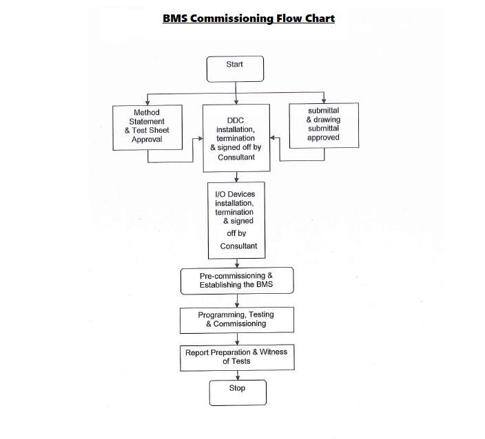
All controls and programming will be done by supplier.
BMS will integrate the monitoring points and will show on graphics.
Sump/Ejector pit Pumps
BMS monitors the following points via Volt free contact (in Control Panel).
- Pit level Status
- Auto Status
- Run Status
- Trip Status
Booster Pumps
BMS monitors the following points via Volt free contact (in Control Panel).
- Auto Status
- Run Status
- Trip Status
- System Pressure by sensor
Recirculation Pumps
BMS monitors the following points via Volt free contact (in Control Panel).
- Auto Status
- Run Status
- Trip Status
Fire Pumps
BMS monitors the following points via Volt free contact (in Control Panel).
- Auto Status
- Run Status
- Trip Status
Water Tank
BMS monitors water tank level in meters.
Chilled water Cooling Unit
BMS will integrate with unit via ModBus to BACnet MS/TP Gateway.
Chlorine Dosing System
BMS monitors the following points via Volt free contact (in Control Panel).
- Chlorine level by sensor (By others)
- Filter Status
- Common Alarm
- Power status
- Pump Run Status
- Trip status
- Auto Status
Generator
BMS will integrate with unit via ModBus to BACnet MS/TP Gateway
Motorized Fire/Smoke Dampers
BMS monitors the damper On/Off status via Volt free contact.
Sharing is caring:

Discover more from Electrical Engineering 123
Subscribe to get the latest posts sent to your email.