
This Method statement details the procedure of installation & testing of earthing system, grounding systems and lightning protection system. The grounding earthing system and lightning protection system are designed to ensure the complete safety of both persons and equipment throughout the buildings covered under the electrical project scope.
Arrange following material and equipment before starting the earthing and lightning protection installation.
-
- Copper earth rods
- Bare copper cable
- Cable clamp for earth rod and copper cable
- Copper tape and clips
- PVC pipe
- Concrete grounding pit.
- Cable lugs
- Air terminal
- Earth bar with disconnecting link
- Exothermic Welding Set
- Earth Tester
- Field Tester
Other References that can be used for technical guide, include:
Project Specification
Shop drawings
Vendor’s recommendations/Guidelines
Erico/Eritech Caldweld™ Exothermic Welding Manual
CADWELD Lightning Protection Connections Catalog Ref -Catalog A1E
CADWELD® Welded Electrical Connections
CADWELD® Welded Electrical Connections, Quick Reference Product Guide, Pocket Catalog Ref. E782C-NAEN
Type of earthing system connections:
- Connect Bare Copper Conductor to Bare Copper Conductor
- Connect Earth Rod to Bare Copper Conductor Wire
- Connect rebar to bare copper wire
- Connect copper bar to bar copper wire
- Connect cable trays/ladders and pipes to grounding system (Detail of electric continuity for cable tray is available in method statement for trays/ladders installation.)
Material storage and handling
Storage of exothermic welding materials should be in a clean, dry, “NO SMOKING” area and should be restricted to access by authorized personnel only.
Storage condition shall be such that exothermic welding materials are not subject to rough handling or physical damage. Storage shall be in cool place and in condition no humidity and moisture.
All boxes or container of material should be stored in accordance with container (carton) or label marking “This Side Up”
These materials must be stored under shelter to protect the boxes from the elements and raised to protect them from dampness or wet surface.
Detail Procedure of Installation of Grounding System
General & Safety Precautions
Do not connect items except as detailed in instruction sheets. Failure to comply with these instructions may result in improper and unsafe connections, damage to items being connected, bodily injury and property damage.
Do not use worn or broken equipment which could cause current leakage.
Do not alter equipment or material without manufacturer authorization.
When using CADWELD® do not use welding material package if damaged or not fully intact.
When using CADWELD® PLUS, do not tamper with or disassemble the welding material unit.
Make connections in conformance with CADWELD instructions and all governing codes.
Personnel should be properly trained in the use of this product and must wear safety glasses and gloves. Avoid contact with hot materials.
Advise nearby personnel of welding operations in the area.
Remove or protect fire hazards in the immediate area. Provide adequate ventilation to the work area.
Do not smoke when handling starting material. Avoid direct eye contact with “flash” of light from ignition of starting material.
Welding material is an exothermic mixture and reacts to produce hot molten material with temperatures in excess of 1400°C (2500°F) and a localized release of smoke. These materials are not explosive. Ignition temperatures are in excess of 900°C (1650°F) for welding material.
Adhering to the CADWELD welding procedures will minimize risk of burns and fire caused by hot molten material spillage. In case of fire, use of water or CO2 will aid in control of burning containers. Large quantities of water will aid in controlling a fire should the exothermic materials become involved. Water should be applied from a distance.
Make sure there is proper mold fit and assembly of equipment.
Avoid moisture and contaminants in mold and materials being welded. Contact between hot molten metal and moisture or contaminants may result in spewing of hot material.
Base material thickness must be sufficient for the size and type of connection being made to prevent melt-through and leakage of hot molten metal.
Applications or conditions may exist which require special considerations. The following are examples, but are not intended to be a complete listing of applications/conditions.
Installation of Exothermic Welding System for lightning protection & earthing system
The mould crucible with suitable size shall be used for exothermic welding. The following procedures shall be followed before conducting the exothermic welding.
- Ensure that the mould is always clean and free of moisture.
- Ensure that the tap hole is always in well-defined condition.
- Ensure that the correctness of connection selector.
- Ensure that the correctness of welding powder
- Procedure to conduct the exothermic connections.
- Fix the connection selector to the handle clamp as per the require sizes of conductor to be welded.
- Place the conductor in the mould; ensure that connection selector is used in accordance to the conductor to be welded.
- Close the handle clamp and lock in the lock position, drop the metal retaining disc into the bottom of the mould crucible. Ensure that the metal retaining disc is correctly, completely seated and cover up the tap hole.
- Deposit the welding power into the crucible and spread a little amount on top of the mould edge as a role of starting power.
- Close the mould lips, and ignite with the flint gun.
- Open the mould after a few seconds where the reaction is completed or the metal has been solidified.
- Do not touch the welding surface after the reaction.
- Clean up the mould for the next joint.
Earthing Cable Installation:
The earthing conductor, bare copper cable shall be installed as per approved shop drawing.
Ensure that the copper cable is straight (not wavy) so that it fits nicely into the exothermic mould prior to the exothermic welding.
Ensure that the copper cable is free of dirt / oil and dry keeping.
Earth Rod Installation:
- The copper rod is to be driven into the ground by means hammer drill / sledge hammer.
- Make sure the rods are coupled with coupling and driving studs before hammering as it will protect the thread or the head of the rods from damaged.
- After the desired depth has achieved, the earthing conductor will be joint to the earth bar / rod clamp of the earth pit and fastened it securely.
- Resistivity check should be taken and if the resistivity is not achieved to required value then it is advisable to drive it deeper.
- The rod shall be driven as deep as possible and does not force to drive it as it may break the coupler and loose the rod.
- The number of rods driven into the ground will be dependable to the soil resistivity on that particular area and as per approved shop drawing.
Earth Pit Installation
Install the inspection pit and ensure that it is flush with the external ground / road level. Ensure that the earth pit is free from dirt and rubbish.
Execution work for Earthing of Lightning Protection
- Drive the earth rods into the earth by hammer.
- Excavate a trench (D x W: 800:500) to link earth rods together by soft drawn bare copper wire.
- Link earth rods to Grounding network.
- Backfilling the trench.
- Testing and record earthing resistant value.
- Joints shall be protected against rust by cold galvanized paint.
- Contact surfaces shall be flush prior to jointing.
- Bolt connections of copper wire with hot dip galvanized steel bar and copper wire with copper bar should reach mechanical effect and electrical effect.
- During the driving of the rods into the earth, it is better to measure value of the resistance to earth in order to quantity of necessary grounding rod.
Handling of chemicals to reduce soil resistivity
- Prepare wiring trench
- Ensure no garbage on the trench
- Put the chemicals along the track covers a thick layer of copper 3mm
- Backfilling the trench.
Procedure of installation of Lightning Protection system:
- The installation of the lightning arresters will be closely coordinated with Apron Floodlight and roofing works.
- The Grounding system for Lightning protection system must be established prior to install Lightning protection system (refer to item 4.4 for Grounding installation).
- The down-conductor shall not be isolated nor enclosed in PVC pipe and placed internal in the apron lighting towers.
- The down conductor should be fixed with a test joint in a position that is convenient for the tests but shall not be reached by irresponsible persons.
- The down conductor 95mm2 bare copper wires shall be connected directly to the mounting base of the lightning arrester by terminal lug.
- The lightning arrester should be fitted into the mounting base before lifting them and connecting to the Apron Floodlight Mast.
- After completing the installation of Lightning arrester into the Apron Floodlight Mast, it shall ensure that the down conductor connecting immediately to the mounting base and the grounding system.
Standard Requirements for earthing system
Down conductor for air terminal (ESE type) shall be connected to earthing rods to ensure direct connection to earth of any stroke current before interconnection with the general Grounding System.
All equipment connected to power supply must be grounded.
All metal parts, structural steel, cable trays, piping, reinforced concrete must be grounded.
All joints shall be according to shop drawing.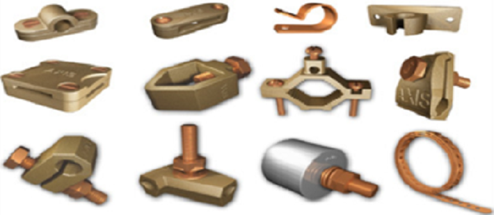
Safety control:
-
- To secure an exit entrance whenever it has contingencies.
- Keep water out where is necessary.
- To keep workplace and amenities is always clean.
- Barricade and sign post are available around the site work.
- To pay attention to equipment/ tools as below:
- Drill machine: insulation and earthing terminal
-
Cylinders: Pressure Gauge Set shall be inspected by authorities
-
Cutting machine: insulation and earthing terminal
Inspection and Testing Procedures
The Grounding and Lightning Protection System shall be given a visual inspection by the Engineer during the installation.
The Contractor should not allow any backfilling of trenches or pits where these systems are installed before inspection by the Engineer and the appropriate documents are signed.
Material delivered shall be inspected under the Engineer’s supervisor about size, quality and quantity.
After performing, works shall be inspected. Inspection of lightning should be included two steps: check underground system and general. For equipment fitted inside structural work or fix underground shall be checked and inspect before backfilling.
Check Grounding and Lightning Protection.
Shop-drawing approved.
Material approved.
Test method of visual:
-
- Check quality of grounding conductor and grounding electrode delivered on site.
- Check installation (connection, routing, and quantity) according to approved shop drawings.
- Check dimension, level and finishing of foundation of air terminal.
- Check installation according to approved shop drawings and manufacturer’s recommendation.
- Functional Test: As per design and manufacturer’s recommendation.
- Grounding Resistance Value shall be measured.
Field testing of Earthing and Lightning Protection System
Grounding rods shall be tested for ground resistance value before any wire is connected. The test shall be performed in normal dry weather, not less than 48 hours after rainfall.
Ground resistance shall also be measured for each piece of equipment to the ground electrode. Testing shall be with a portable ground testing megger for each ground or group of grounds. The instrument shall be equipped with ammeter reading directly in Ohms or fractions thereof to indicate the ground value of the electrode under test.
All test equipment including test meter shall be provided and one copy of the ground megger manufacturer’s directions, including the method shall be provided.
The minimum resistance based on the allowable capacity of the conductor shall be as indicated in the following table:
Resistance tests table
| Amperes/ | Ohms |
| 25 through 50 | 250000 |
| 51 through 100 | 100000 |
| 101 through 200 | 50000 |
| 201 through 400 | 25000 |
| 401 through 800 | 12000 |
| Over 800 | 5000 |
The earth resistance shall be measured either soil resistivity testing or earth resistance testing method.
Soil resistivity testing based on Wenner method
Equipment and procedure for soil resistivity:
The test instrument is used Mega Digital Earth Tester. The instrument is connected to the electrodes as detail below:
Four electrodes are driven into the ground, in a straight line with equal spacing between them.
Let the spacing be called ‘a’.
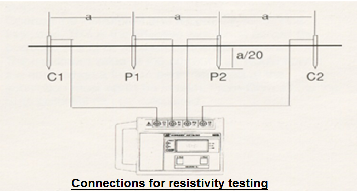
The soil resistivity can then be calculated using the equation:
ƒ = 2 x 3.14 x a x R
Where ƒ = soil resistivity (ohm meters)
a = electrode spacing (meters)
R = measured resistance (ohms)
Soil Resistivity Testing Procedure
- Confirm the proposed test locations.
- Insert four electrodes into the ground in a straight line a= 2 meters spacing. Connect instrument to the electrodes as shown above.
- Perform test and record measured resistance in Soil Resistivity Test Form.
- Shift electrodes to next spacing a= 4 meters and repeat test.
- Repeat tests a= 6 meters, 8 meters and 10 meters electrode spacing.
- Recorded measurements will be analyzed and presented in Soil Resistivity Test
After finishing the installation works of Grounding and Lightning Protection System, inspection shall be carried out and approved by relative parties such as: Consultant, Main contractor. We can ask the Experiment Center for inspection the whole system and then issue the Certificate Completion.
Safety control method:
The safety procedure generally has to be applied for all Engineers, Supervisors, and Workers as following bellow:
- Make sure that all personal protection equipment (PPE) be provided on site before starting work such as helmet, safety boot, safety glasses, glove, mask etc.
- Make sure that PPE must be wear in the correctly way when working.
- Tools and equipment shall be inspected by authorized person before carried out the work.
- Barricades and sign posts for warning shall be provided on site.
- Fire extinguishers shall be provided on site wherever exothermic welding works and always ready to use.
Working safely during exothermic welding:
- Ensure worker wear safety glasses, gloves, helmet etc.
- Fire extinguisher shall be always ready at work place
Working at height:
- Ensure every worker wear safety harness when working at more than 2 m height.
- Safety protected handrail on top layer of scaffolding shall be provided.
- Ensure A ladders are in good condition/quality.
Sharing is caring:

Discover more from Electrical Engineering 123
Subscribe to get the latest posts sent to your email.