
This page provides steps for successful installation of medium voltage electrical switchgear panel on a construction project or building.
The method of statement describes the procedure for material delivery inspection, installation and inspection of MV switch gears.
Project Manager is the overall responsible person for the process of implementation of the work methods.
The Construction Manager/Site Engineer will be responsible for all construction activities at the site and will directly supervise through erection supervisor/skilled workmen at the work site.
Site electrical & QC engineers will be responsible for arranging and controlling the inspection and testing activities.
Furthermore, is is the responsibility of each individual employee in the project to take due care to ensure their own personal safety and his coworkers.
This procedure involves below steps:
- Preparation of the works
- Delivery and inspection of MV Switchgear
- Setting out of works
- Installation of MV Switchgear
- Inspection of MV Switchgear
Below is list of equipment that you will need for the switchgear installation works:
- PPE for all staff and labor
- Measuring tape and setting out markers
- Drill Machine
- Mobile Crane or Chain Block
- Hand Tools
- Electricians tool box
Preparatory Installation Conditions & Requirements
Prior to installation of MV switchgear, the supervisor and foreman will verify and ensure that all safety requirements have been complied with and are in place.
Electrical supervisor will verify that all relevant approved latest revision of shop drawings, technical submittals, inspection and test plans are available in the work place for installation reference.
Also make sure that switch gear installation procedures and manufacturer guidelines are available on the project site.
The supervisors and foreman will inspect all the materials delivered to the work place and ensure that these are correct and free of any damage or defect.
Materials that are not as per requirement or with damage or defect will be set aside. These will be properly labeled and returned to the warehouse.
Store all materials or panels in a clean I dry place and provide adequate covering by tarpaulin sheets to protect the equipment from deposition of construction dust till final shifting to its location for installation of panels. Also consider the manufacturer recommendations for storage and handling of the electrical panels.
After receiving the materials on construction site, quality engineer shall inspect the materials as per ITP and checklists. This will help to verify that all switchgear panels are as per material technical submittals in terms of make, model, type, country of origin, size and capacity etc.
Supervisor / foreman will orient and familiarize all the technicians and labors regarding relevant approved shop drawings, technical submittals, panels installation procedures, acceptance criteria, safety requirements and any other details.
Installation supervisor will examine surfaces / plinths to receive the MV switchgear for compliance with installation tolerance and other required conditions, as described in the installation requirements. Installation will not proceed until satisfactory conditions have been achieved and any defects are corrected.
All installation/ Construction/ Testing works shall be carried out in compliance with the correct specifications and project safety manual.
Medium Voltage Switchgear Installation Procedure
Ensure that concrete bases and foundation trenches provided for installation of equipment are constructed in accordance with approved drawings and equipment manufacturer’s drawing and that holes for fixing bolts and provisions for passage of cables are provided as required.
Bring the base frames or panels on the locations using approved lifting method.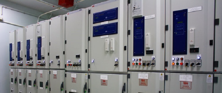
Place the panels as per drawing plans, schematics, coordination drawings and diagrams indicating location and arrangement of MV switchgear panels.
Remove temporary lifting eyes, channels, and brackets and temporary blocking of moving parts from main distribution board on units and components.
Ensure that trench construction and covers provided for installation of power and control cables are in accordance with approved shop drawing.
Ensure that equipment supports, fixings and the like, and sleeves for passage of feeders and cables which are to be built into foundation, bases, cable trenches or building structure are provided as and when required and that they are properly Installed.
Install the switchgear panels components on concrete bases and assemble completely plumb and level, before grouting in holding-down bolts. Installation to be inspected and certified as “Fit for energization” as per manufacturer I authorized representative.
Install all incoming and outgoing cable supports, cable ends and termination fittings required for power and control cables.
Tighten the electrical connectors and terminals, including grounding connections, according to manufacturer published torque tightening values.
Connections are to be made at front of terminal board and with no live metal exposed. Wire termination to be carried out with end-lugs I ferrules.
Wiring is to be modularly and neatly arranged on master terminal boards with suitable numbering strips and appropriate cartridge type fuses where required. All control wiring is to be neatly enclosed in special trunking and secured in place.
Set the relays, timer and other breaker in accordance with manufacturer’s instruction and in accordance with an approved scheme.
Minimum clearance of 800 mm shall be maintained at rear side of the panel for providing easy access for termination of cables and other maintenance works.
Frame and mount the printed basic operating instructions for main distribution boards, including control and key interlocking sequences and emergency procedures.
Fabricate frame of finished wood or metal and cover instructions with clear acrylic plastic. Mount on front of main distribution boards.
Battery Charger Installation Method
Determine the preferred layout and ensure the socket-outlet is located near the equipment and easily accessible.
Ensure the unit is plumb then mark through the four screw holes to identify where the pilot holes will be drilled.
Using a 1/16-inch bit, drill pilot holes at the marked locations.
Mount the unit using the pan head screws.
Route and connect all cabling to the appropriate device. Use cable tie down as needed.
Connect the ground stud using the most direct route to known equipment ground source.
Battery Rack Installation
Consider available space, including aisles for cell installation, maintenance, and possible cell replacement.
Locate racks to minimize temperature variation between cells. Do not locate the battery near HVAC ducts of exhaust, heat sources (i.e.,equipment that generates heat or direct sunlight).
Adequate ventilation must be provided. Do not Install in an air tight enclosure or room with no ventilation.
Mark location for anchor bolts using the holes in the bottom of each frame. Install floor anchors in pre-determined locations.
Align rack with floor anchors and attach to floor. Shimming up to 0.25 in. (6mm) maximum may be required to level support rails both front-to back and side-by-side. Recheck all bolted connections for proper torque as directed in manufacturer’s instruction.
Place frames at the floor locations. Attach cross braces to frames for strength and rigidity between the frames.
Bolt cross braces together where they cross each other. Make sure frames are plumb before tightening bolts to the required torque.
Attach the support rail to assembled frame. Place rail on frame clamp nut, push bolt assembly upward. Rotate clamp 90 degree fasten bolt.
Position each rail so the overhang beyond the frame is equal to each end of the rack,or as specified on the rack assembly drawing.
With the frame, braces and rails assembled, check frame alignment, torque all bolts as indicated.
Attach corner brackets to end rails to prevent batteries from falling off end to rack during a seismic event.
Ground rack according to local codes. Periodically check the ohm meter to determine that all components of the rack are still grounded. If the ground becomes lost on any component, loosen one bolt at a time and tighten to the original torque value. Continue to do so until continuity has been reestablished.
Panel Board Installation
Install panel boards and accessory items according to approved shop drawing & manufacturer’s installation requirements.
Check the panel configuration and arrangement of components and wiring with approved schematic diagrams.
Mounting heights shall be 1800 mm above finished floor unless otherwise indicated in accordance with the approved coordinated equipment location drawing.
Plumb and rigid without distortion of box. Mount flush panel boards uniformly flush with wall finish.
Terminate the cables to panels after meggering & check the tightness of the cable terminations.
Complete earth terminals of all components and their related connections.
Type directory to indicate installed circuit loads after balancing panel board loads. Obtain approval before installing.
Identification of cables to be provided at ends.
Clean panels with vacuum to remove all foreign matter.
Protect the panels from dust & construction debris.
Inspection and Testing Procedure
Ensure that all instruments and devices intended to use for testing must be calibrated. Attach all calibration certificates in the work inspection request showing the date and record of calibration.
Ensure installation of MV Switchgear assembly carried out in accordance with manufacturer’s installation recommendation, requirement of applicable standards and in accordance with recognized industrial practices and specified project specification.
Check physical properties of MV switchgear system if free from any damages or defects.
Prior to switchgear panel energisation, installation shall be checked and inspected by authorized representative from manufacturer.
Test result shall be checked and signed by the QC Engineer, Site Electrical Engineer and consultant.
Periodic inspections of the entire battery rack are to be made to observe any signs of acids corrosion. When corrosion is detected, scrape away the corrosion to bare metal. Neutralize the area with the solution of bicarbonate soda and water (1 pound of soda to 1 gallon of water), dry and then paint the area with acid-resistant paint.
Sharing is caring:

Discover more from Electrical Engineering 123
Subscribe to get the latest posts sent to your email.