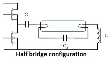
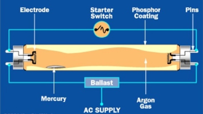
Fluorescent light electronic ballast provides initial high voltage for discharging the gas inside the fluorescent lamps/bulbs.
Ballast converts power frequency to very high frequency that initializes gas discharge process by controlling voltage and current through the lamps.
There are different types of light ballasts which include electromagnetic, hybrid and electronics.
On this page we are talking more about the electronic ballasts which mainly provide the startup voltages.
After that it maintains constant current and assures that the circuit will remain stable.
As we know that normal electricity comes with frequency of 50 – 60 Hz which electronic ballast increases and supplies to the lamp at a frequency of 20,000 Hz or higher.
The benefit of this is that it eliminates the stroboscopic effect of flicker which can be due to line frequency associated with fluorescent lighting.
Principle of Electronic Ballast
Electronic ballasts are often based on the SMPS topology, first rectifying the input power and then chopping it at a high frequency.
Advanced electronic ballasts may allow dimming via pulse- width modulation or via changing the frequency to a higher value.
High output frequency of electronic ballast refreshes the phosphors in a fluorescent lamp so rapidly that there is no perceptible flicker.
The flicker index is used for measuring perceptible light modulation ranges from 0-1, with 0 indicating lower possibility of flickering and 1 indicating the highest.
With the higher efficiency of the ballast itself and the higher lamp efficacy at higher frequency, electronic ballasts offer higher system efficacy for low pressure lamps like the fluorescent lamp.
Types of Electronic Ballasts
There are mainly three types of electronic ballast i.e. instant start, rapid start and programmed start.
- Instant start electronic ballasts start lamps without delay (<0.1 seconds) or flicker by providing a starting voltage that is sufficiently high in order to initiate the discharge through the lamps without waiting the need for heating lamp electrodes. For this types of ballasts the starting voltage is about 600V. Lamps associated and operated by instant start ballasts typically operate 10,000 to 15,000 switch cycles before failure.
- Rapid start electronic ballasts start lamps quickly (0.5– 1.0 seconds) without flicker by heating the lamp electrodes and simultaneously applying a starting voltage. Lamps operated by rapid start ballasts typically operate 15,000 to 20,000 switch cycles before failure.
- Programmed start electronic ballasts are best option to provide maximum lamp life in frequent lamp starting applications such as in areas where occupancy sensor controls are used. Lamps operated by programmed start ballasts typically operate up to 50,000 switch cycles before failure. Hence providing the maximum life span.
How Electronic Ballast Functions
Electronic ballast uses solid state electronic circuitry to provide the proper starting and operating electrical conditions to power discharge lamps. The ballast may be “potted” with a resin to protect the circuit boards and components from moisture and vibration.
There are different types of light ballast circuits i.e. self oscillating and IC driven circuits. Also a new Capacitor Couple Converter (CCC) circuit developed at the HKU Power Electronics Lab is becoming famous.
Electronic ballast can be smaller and lighter than a comparably-rated magnetic one. Electronic ballast is usually quieter than a magnetic one, which produces a line-frequency hum by vibration of the transformer laminations.
Main technical characteristics & Benefits are:
- Start performance is good at low pressure condition, can start smoothly, and preheat tubes after a starting point, to avoid The Times.
- Adaptive voltage range
- Preheats the startup that greatly prolongs lamp life, reduces costs, and enhances environmental protection.
- High power factor, all specifications achieved 0.98.
- Pressure, flow and output abnormal state protection function
- Eliminates strobe light, more stable. To improve vision, improve efficiency, reduce the resolution of continuous operation visual fatigue, help protect eyesight.
- Low noise, lightweight.
LED lighting is the new trend which is now leading the optical industry, which is one of the world’s most energy- intensive sectors. In addition, it has become the most important axis of “Low-carbon Green Growth” industry due to its high-energy efficiency and long life, and has been diversely expanding its application field to electricity/electronics/lighting, and so forth as the key industry of green contents that IT technology and semiconductor technology are integrated.
Technical Specifications of Different Types of Ballasts
High Frequency Electronic Ballasts (Fixed Output):
The operating temperature range should be -25ºC to +50ºC but preferably +60ºC.
a) The ballast should have constant light output independent of voltage fluctuations in mains voltage (198-254V)
b) It shall be operating in the voltage range 198-254V 50/60Hz
c) The ballast shall be suitable for DC voltage in the range of 154-310V (lamp start 200-310V).
d) The ballast shall have a non-audible noise level less than 28dB.
e) The ballast shall have a power factor of > 0.95
f) Every ballast shall be distinctively marked with the month and year of manufacture in addition to the standard markings. The standard markings have to include country of origin. Only European, U.S.A. and Australian country of origin is acceptable.
g) The operating frequency has to be equal or greater than 42kHz.
h) It must have safe switch off of defective lamps and safe shut down when the lamp comes to the end of its lamp life
i) It must have automatic re-start after lamp replacement.
j) The ballast must have overvoltage protection 320V AC for 1 hour
k) For safety reasons the ballast has to start within the following time:
i. 0.5 seconds for T5 lamps
ii. 0.9 seconds for T8 lamps
iii. 1.5 seconds for TC-L compact lamps
iv. 1.0 seconds for TC-D, TC-S, TC-T compact lamps
l) The T5 ballasts must have built in cut-off technology (cut-off of the filament heating)
High Frequency Electronic Ballasts (Dimmable):
a) The ballast shall have constant light output independent of fluctuating supply voltage
b) The ballast shall be switched via the mains or with digital control signal
c) It shall have dimming which is comfortable to the eye (logarithmic dimming curve)
d) The ballast shall have a disturbance free precise control with a digital signal (DSI) or/and be able to be controlled by a standard push-to-make (momentary/bell press) switch
e) It shall have fully electronic lamp management and digital communication with ASIC, thereby ensuring:
i. Safe switch off of defective lamps
ii. Safe shut down when the lamp comes to the end of its lamp life
iii. Automatic re-start after lamp replacement
iv. Reliable start of the lamp without nuisance flickering and noise
f) The ballast shall have a non-audible noise level less than 28dB.
g) The ballast shall have a power factor of > 0.92
h) The operating temperature range should be -25ºC to +50ºC but preferably +60ºC
i) Every ballast shall be distinctively marked with the month and year of manufacture in addition to the standard markings. The standard markings have to include country of origin. Only European, U.S.A. and Australian country of origin is acceptable.
j) The operating frequency shall be –40-100kHz
k) For safety reasons the ballast has to start within the following time:
i. 1.5 seconds with AC and 0.6 s with DC for T5 and TC-DD lamps
ii. 0.6 seconds for T8 lamps
iii. 0.6 seconds for TC-L, TC-F compact lamps (with 1x55W, 2x55W, 2x18W in 1.5 s with AC)
iv. 0.6 seconds for TC-D/E, TC-S/E, TC-T/E compact lamps
l) The dimming range shall be as follows:
i. 1-100% for T5 lamps
ii. 1-100% for T8 lamps
iii. 3-100% for TC-L, TC-F, TC-D/E, TC-T/E, TC-S/E, TC-DD lamps
m) The T5 ballast must have built in cut-off technology (cut-off of the filament heating)
LED Drivers Technical Requirements:
The LED driver(s) shall meet the following requirements:
a) Drivers shall have a minimum efficiency of 85%.
b) Case (Tc °C) Temperature rating -40°C to minimum +80°C and at a minimum 95% Relative Humidity (RH).
Driver/Fixture to have some means of built in overheat thermal protection in the form of automatic dimming or stepping/holding down of the driver where temperature exceeds operational limits, Thermal cut-out devices which turn the fixture LEDs completely off are not acceptable.
The Driver and driver output current must be shown to be fully tested and compatible with the exact LED chips/engine of the luminaire.
All information provided and the cost analysis/payback calculations should be calculated with the exact drive current including the calculation for the life cycle, life and resultant increase or decrease of the energy consumption if applicable.
c) Input voltage; capable of 120-277 volt, single phase or as required by the site.
d) Power supplies can be UL Class 1 or II output or similar European CE or International equivalent.
e) Surge protection: Must be tested in accordance to the requirements of IEEE/ASNIC62.41.2-2002, Scenario I Location Category C or International equivalent.
f) Drivers shall have a Power Factor (PF) of L: ≥ 0.90. Drivers shall comply with FCC 47 cfr part 18 non-consumer RFI.EMI standards or equivalent.
g) Drivers shall have a total individual luminaire Harmonic Distortion (THD) of: ≤ 10% in accordance with ANSI C82.77 (2002).
However the Contractor shall measure the harmonic at the supply point (LV side of the distribution substation) after the installation of all the LED street lights and adopt harmonic compensation methods to limit the total harmonics distortion in the supply voltage to maximum 5% as per IEEE 519 Regulations.
Discover more from Electrical Engineering 123
Subscribe to get the latest posts sent to your email.
