
Prior to commencement of work, all shop drawings will be submitted for approval by consultant/client.
Shop drawings will show the layout of pipe and cables as well as the section drawings.
Only approved shop drawing will be used for installation.
All materials to be used will be submitted for Engineer’s approval in forms of Material submittal or Product Data. Only approved material will be stored and used in site.
The purpose of this method statement is to define the sequence and working methodology of installation of the following activities.
MV Cables installation (External & Internal services or wherever required) and LV Cables installation for:
- Building Services
- Street Lighting
- External Lighting
- Telecom & ELV Cables
References and Standards
- Contract Specifications for cable infrastructure including Telecoms and BMS cables
- Approved Material Submittal
- Approved shop drawings
- Inspection and Test Plan
- Project Safety Plan
- Project Quality Plan
- Project Logistics Plan
- QMS Procedure
- JSEA
Necessary Plant and Equipment
- Electrician hand tools
- Steel pull spring
- Cable rollers
- Cable drums jack
- Handling equipment of drums
- Calibrated megger & multimeter
- Hydraulic cable cutter
- Winch motor where as required location
- Cable basket
- Cable pulling compound
- Power Supply: Single-phase normal power where it is needed.
- Survey equipment
- Spirit Level
- Chipping hammer
- UPVC Glue
- Crimping tools
- Two way radio for communicating tools during cable pulling activity
Roles & Responsibilities
Package project manager will be overall responsible for complete MEP works.
Site electrical engineer will be responsible for the all containment and cable pulling works.
Foremen will control and guide workers and will report to the site engineer.
Safety Engineer will be responsible for monitoring and assurance of safety and environmental requirements as per job safety analysis (JSEA).
Quality Control Engineer will be responsible for the implementation of the relevant method statement and ITP.
Material Storage & Handling
Upon receipt of materials at project site, crane will be used to unload the cables and store them in laydown areas adjacent to the correct staging area.
Ensure that the cables received are as per the purchase order and project specifications. Delivery will be checked and confirmed as per approved material submittals and technical specification.
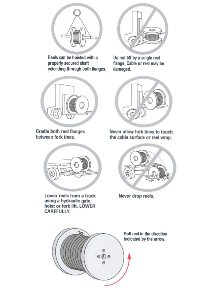
Reasonable care will be taken at all times while off-loading the cable drums. They should be lowered down slowly through crane /forklift and will not be dropped at a sudden pace.
Protective covering will be inspected for evidence of any shipment damages.
Cable end must be originally sealed off from factory with the end caps.
Cable Reels will not be stored flat but to keep upright position on their flanges.
Material will be stored in accordance with the manufacturer’s recommendations usually consisting of a covered dry location at all times to avoid corrosion.
Receiving inspection of materials will be coordinated with QA/QC engineer for Materials Inspection Request (MIR).
Only approved materials will be stored at site.
Every material delivery will be inspected.
Shipments certificate shall be attached to the inspection request.
Handling Procedures:
Identify the cable drums and location to transport as per approved shop drawings. Appropriate cable drum trailers are to be used for pulling the cables.
Lift the cable reels in such a manner that the lifting/handling device does not make contact with the cable or its protective covering.
Handle the reels in a manner that prevents deterioration and physical damage to it and to the cables.
The following lifting methods are recommended:
Insert a suitable properly secured spindle through the reel arbor hole and lift the drums with appropriate slings, using a crane or a boom type equipment to place the drum on the cable drum trailer.
Move smaller, narrower reels using a forklift.
Place fork tines so that lifting pressure is on both reel flanges, not on the cable.
Hydraulic cable drum jacks can also be used with the same method as mentioned above.
Precautions:
To prevent damages to the cables proper care should be taken from severe blows with sharp instruments.
Do not pull cables around the corners that have sharp edges.
Provide a cable roller as support in every corner to protect the cable insulation damaging during cable pulling works.
Do not pull cables at a radius smaller than the recommended pulling radius.
Make sure all equipment’s used during cable installation are in good operating conditions.
Use cable roller to avoid damages to the cables in every sharp bend/corners.
Cable installations must be preplanned to ensure a successful installation.
It is important to ensure that personnel are properly trained and qualified for the specific task they are performing.
Excavation/Trenching Procedure
Excavation/Trenching has to be undertaken by the civil contractor as per the approved method statement of excavation, trenching and approved backfilling materials.
Before going to the execution of excavation procedure, the area will be properly barricaded and protected to prevent workers injury/accident during the time of construction.
Excavation will be made by open cut to indicate gradients, lines, depths and elevations.
Excavation will be completed to below grade elevations regardless of the character of the surface and ground conditions encountered, including rock and obstructions.
Trenches will be excavated to sufficient, uniform widths to provide free working clearance on each side of the structure for concrete forms if required.
Bottom of excavations will be uniform and free of projecting rocks and sharp objects.
Pre-Installation Procedure (MV Cable, LV Cable, Telecom & ELV Cable)
submit IR for BH approval to verify routs of utility
Route identification and marking work mechanical and electrical services.
Minor deviation from the approved construction drawing and MEP drawing would be determined on site with the consent of consultant site staff and changes to be reflected in as built drawing for future reference.
All material and documentation relevant to this particular section of work shall be checked prior to installation.
Check the area where in the works to commence are ready, accessible and suitable for permanent works.
Check the tools to be used for cable pulling such as cable winch where ever required cable pulling rollers, grips, stands, jacks etc. are ready suitable in site and on good condition.
MV/LV Cable Pulling and Installation
Install the MV cables in accordance with local standards and approved project specifications.
Cable drums to be set on jacks and bars of sufficient size and weight bearing loads, adjacent to the trench to ensure the cable is running parallel with or inside the trench along its longest length.
Two operatives to control brake at the cable drum to ensure it does not over run.
Good communication will be maintained at all times between “front to cable drum “especially over long distances.
Close supervision will be applied to make sure that over stressing of the cables does not occur.
Cables will be pulled smoothly and maintained at a reasonable rate to ensure control and tension requirements are met and to ensure no snagging may occur.
A cable winch may be required to assist long heavy pulls. The winch is to be operated by competent personnel only.
Cable rollers may also be used, set out at equal distances along its length to assist long heavy pulls.
Cable basket to be used to assist the winch and to help in avoiding damage of the insulation during cable pulling.
Observe special attention where the trench changes direction to ensure that the minimum bending radius of the cables is not exceeded.
All excessive loose materials including broken rocks or concrete debris which has sharp edges shall be removed from the trench prior to the installation of cables.
No foreign debris allowed prior to start of backfilling activity inside of the trench, sand bedding to be properly level.
Once installed, cables are to be checked along full length for damage prior to back filling by the civil contractor make an internal retest tabulation recording of the cable for the insulation for future references.
Cable Checking, Verification and Backfilling
Depending on the cable length, joints may be required and installed at pre determined locations as detailed on approved drawings prior to approval of the engineer.
Cable cut sheet schedule to be strictly considered and be monitored.
Prior to backfilling works raise inspection request for site compliance and verification works of the contractor.
Cable jointing will be carried out by authorities approved contractor and cable joinery.
Prior to backfilling, remove end caps and bare back the insulation to reveal the inner copper cores.
Using 5000V insulation resistance tester, testing will be carried out between each core and the outer sheath to ensure continuity and resistance are satisfactory.
All test results will be recorded using the approved test sheets.
If the same trench has more than one cable, above procedure will be repeated.
Trench bedding materials shall consist of fine sand with granular material compacted in 200 mm layers and complying as what the trenching detail approved submittal specified requirements.
After compacting, referring to the passable approval passing table allowable ratio red tile will be placed 300mm above the cable for its protection.
Backfill materials will be compacted in 200mm layers in the trench.
Warning tape will be provided along the cable routes 300mm above the concrete tile as per approved shop drawing details.
If excavated materials are kept for backfilling, remove all materials such as large or sharp rocks and debris etc.
Place backfill in excavations promptly but not before surveying locations or utilities for record documents and inspecting/testing underground utilities.
Backfill shall be brought up to final grade in approximately 150mm compacted lifts to a smooth surface from irregular surface changes.
Excavations under paved areas shall be backfilled as above except that each lift shall be moistened and compacted to a density at least equal to that of surrounding earth and requirements of excavation under roadways.
Where settlement occurs prior to end of project correction period, excavation will be reopened to required depth refilled and compacted.
Evidence of restoration will be eliminated to greatest extent possible.
Proper cable route marker shall be installed as per standard and approved shop drawing.
After the installation is completed, an Inspection Request will be formally raised to the Engineer to ensure accuracy and high quality of works.
The cable shall be kept clear of other services and piping.
Physical separation between cables and other pipes shall not be less than 300mm.
When multiple cable runs occur the cable shall be installed in such ways that crossover of cables are avoided.
Telecom and ELV Cables Installation
Utilize the nylon cord which is connected between manholes and pull the fiber optic as well as ELV network cable through the concern UPVC duct.
Extra care shall be taken care while pulling the telecom and ELV cables.
Before pulling, make sure that all Upvc ducts are free from any particles, sand and debris.
Mandrel the pipes end to end prior to cable pulling to assure removal of any obstruction and to avoid clogging during cable works.
After the installation is completed, an inspection request will be formally raise to the consulting engineer to ensure accuracy and high quality of work.
The cable pulling shall be subjected to consultant’s prior approval.
Cables shall not be bent during installation.
Make sure that all cables run from point to point without joints.
All cable ends to be properly tagged for identification and reference.
After the installation is completed, an inspection request will be formally raised.
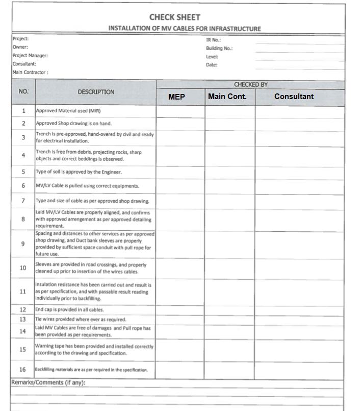
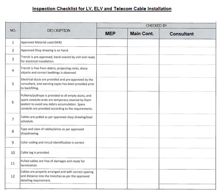
Inspection Checklists
Sharing is caring:

Discover more from Electrical Engineering 123
Subscribe to get the latest posts sent to your email.