If you need to learn everything about thermoelectric generator then this page is for you.
Thermoelectrical power generator is a solid state device that facilitates direct conversion of thermal energy into electrical energy.
Thermoelectric generators function like heat engines, but are less bulky and have no moving parts and are completely silent.
The best part is that, by using he thermoelectric generator we are able to directly convert waste heat to electrical energy, without involving additional processes, movements or energy losses.
In automobiles a thermoelectric generator (TEG) is a device that converts waste heat in an internal combustion engine (IC) into electricity using the Seebeck Effect.
A typical TEG consists of three main elements:
- A hot-side heat exchanger,
- a cold-side heat exchanger,
- thermoelectric materials.
Automotive thermo electric generators ATEGs can convert waste heat from an engine’s coolant or exhaust into electricity. By reclaiming this otherwise lost energy, ATEGs decrease fuel consumed by the electric generator load on the engine.
The main principle behind this type of electric generator is “Seebeck Effect”.
Before going in further details about the thermoelectric generator lets first learn about the seebeck generator effect.
What is Seebeck Generator Effect
Thermoelectric power generation is based on a phenomenon called “Seebeck effect” discovered by Thomas Seebeck in 1821.
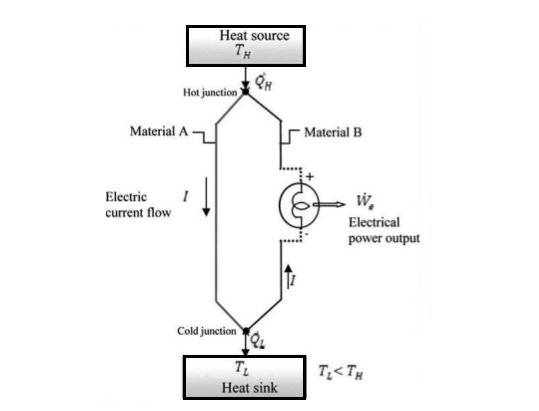
As per his definition, when a temperature difference is established between the hot and cold junctions of two dissimilar materials (metals or semiconductors) a voltage is generated, that is known as Seebeck voltage.
Q(h)= high temperature heat transfer
T(h)=high temperature
Q(l)=low temperature heat transfer
T(l)=low temperature
W(e)= output energy
W(e)=Q(h)-Q(l)
Construction & Working of Thermoelectric Power Generator
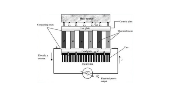
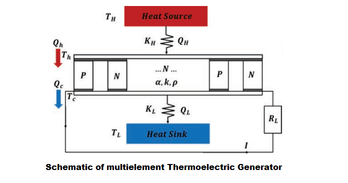
A thermoelectric generator is made up of many pairs of p-type and n-type elements.
Holes are charge carriers in p-type which have positive seebeck coefficient while in n-type electrons are charge carriers which have negative seebeck coefficient.
Voltage potential develops across the p-n junction that is proportional to the differences in the Seebeck coefficient in each element and the temperature of the junction.
Electrons as the charge carriers in n-type and Holes as the charge carriers in p-type move from high heated area of the conductor to low heated area of the conductor. Because of the movements of charge carriers current will produce inside the conductor.
There are different sizes conventional thermoelectric devices available both for domestic and commercial uses. Typical sizes vary from 3×4 sq. mm 75×5 sq. mm. Typically these are 50 mm in length.
Height of modules vary from 1mm to 5mm. These thermoelectric modules contain 3 to 127 thermocouples.
There are multistage thermoelectric modules of height 20 mm.
Below you can see a schematic diagram showing components and arrangement of a typical single-stage thermoelectric power generation unit.


Performance of thermoelectric power generator
The performance of thermoelectric devices depends on the figure of merit (ZT) of the material. You can express the performance of thermoelectric materials as per below expression:
Z= a^(2)/kr
where,
Z is thermoelectric material figure-of-merit
a is Seebeck coefficient
k is the total thermal conductivity
R is the electric resistivity
ZT = a T / kR
where, T=T(h)+T(l)/2
Carnot efficiency n = 1- T(l)/T(h)
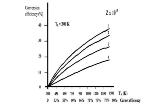
Conversion efficiency as a function of temperature and module material figure-of-merit.
With the increase in the value of T(h) conversion efficiency increases.
But with the increase in the value of Z has an opposite effect on the conversion efficiency.
Benefits of thermo electric generator
- no moving elements
- environmental safety
- no working fluids and gases
- low-noise operation
- reduced size and weight
- high reliability
- guarantees up to lifetimes or more than 200000 hours
- smooth and fine adjustment of cooling capacity and temperature
- resistance to mechanical loads
- operation in any spatial position
- easy switching from cooling to heating mode
Fabrication process of thermo electric microconverters
- The p type Sb2te3 film is deposited by thermal co-evaporation followed by Nickel
-
Photo resist and P type elements are patterned by photolithography.
-
Nickel is etched in chromium etchant, a Thermoelectric film is patterned by wet etching HNO3.HCL and photo resist is removed.
-
The n type film deposited by co evaporation followed by 100m nickel layer.
-
Photo resist is applied and patterned by photolithography for n type element.
-
N type is etched in HNO3 and photo resist is removed, contacts are deposited starting with a layer of nickel followed by 1µm of aluminum and photo resist is removed.
-
A protective layer of Si3N4 can also be deposited by low-temperature hot wire chemical vapor deposition and patterned depending on application.
Materials used for thermoelectric generator
Ceramic Plate made from aluminum.
Hot and cold plates usually connected with highly conductive material like as copper.
Commercial materials: – these materials are further divided in to the three categories.
(a) Low temperature material (around 450K, Material used- alloy Bi combination with Sb,Se,Te)
(b) Medium temperature material (between 450K to 850K, Material used-alloy of Pb)
(c) High temperature material (up to 1300K, Material used-alloy of Si and Ge)
Novel materials reduce lattice thermal conductivity without the typical negative effects on electrical conductivity from the simultaneous increased scattering of electrons.
The most common material used for this generator is Lead telluride. Lead telluride is a compound made of lead and tellurium having small amount of bismuth or sodium.
Discover more from Electrical Engineering 123
Subscribe to get the latest posts sent to your email.
