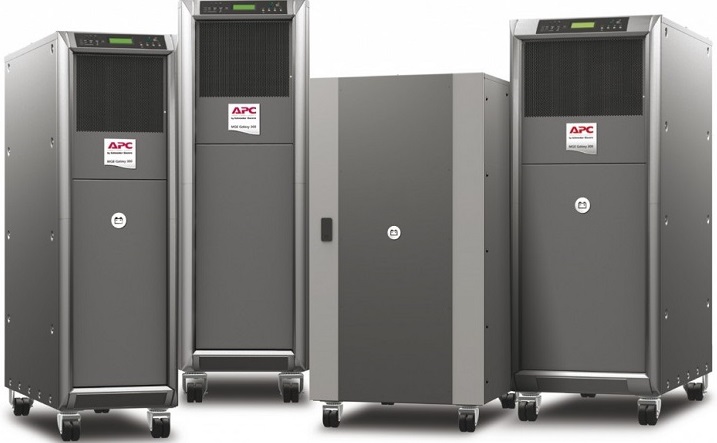
This procedure provides a safe, standardized approach for the initial inspection, checkout, testing, and data documentation of Uninterruptible Power Supply (UPS) and chargers during the commissioning phase.
These tests are intended to check the board and its constituent parts for correct operation. The battery charger is generally used to energize the batteries.
Battery charger shall also provide DC power to battery system. Automatically provide continuity of electrical power, within the defined limits and without interruption. i.e. autonomy time in the event of network failure, shall be determined by the battery capacity.
This method shall refer to single line diagram, schematic diagram & Equipment drawings. Following equipment components shall be under the test:
- Thyristors bridge battery charger
- Electronic static switches
- Control units
- Voltmeter and amperemeter
Necessary Instruments / Tools
Milliohm meter for continuity measurement
Preliminary Checks
Check the marking of battery charger board components.
Make sure that it is not possible to come into contact with energized equipment when working on the system.
Check the main busbar and auxiliary circuits (control, monitoring, alarm, fault) for continuity.
Measure the grounding busbar continuity and connection to the main earthing system.
Check that the panel hinged doors are connected to the frame by earthing braids.
Door locks to be checked for correct operation.
Open all the incomers and load circuit breakers.
Check the connections for conformity with the reference drawings and their tightness.
Electrical Checks & Test
Testing Continuity Between All Metal Parts and Ground: For performing this test, it is generally recommended to use a milliohm meter for continuity measurement.
Insulation Resistance Tests
It is recommended to perform these tests before connection starting so all isolating devices will be opened.
If cables are already connected, open the isolating devices before any test. Disconnect the ground sensing device and the control cables.
Using a 500 V DC mega ohmmeter, measure the insulation resistance after a one minute electrification time between:
- Positive busbar and negative busbar with ground.
- Negative busbar and positive busbar with ground.
- Auxiliary circuit and ground.
Reconnect the cables after testing.
System Checks
Check of manufacturer data
Visual check
Correct labelling of device and cable
Satisfactory access to device
Device and cable undamaged
Correct cable terminations
Correct sealing of cable entries in terminal boxes
Correct protective and grounding connections
Correct power supply
Mechanical Checks
- Grounding connections
- Cable connections
- Terminal blocks
Electrical Function Tests
- Open DC isolators between battery charger and battery /consumers
- Switch on main supply voltage
- Check voltage and phase sequence
- Switch on battery charger AC side
- Check DC voltage in all operating modes
- Check voltage and polarity on both sides of the DC isolator
- Close DC isolator
- Check of annunciation
Testing of Battery Charger Panel Before Energizing
Connect the battery charger and battery supply cables or incoming cables from main distribution board.
Check the presence of the mechanical protectors preventing any accidental contact with live parts. Open all the outgoing disconnecting devices.
Check the distribution board alarm information return up to the output terminal blocks.
Testing/Checking Automatic Transfer Switches
Check mechanical and / or electrical interlocks. Check correct polarities.
With the both available supplies confirm the functional checks by presence of voltage, loss of supply, restoration of supply in manual and in automatic mode.
Placing the UPS / Charger in Service
Check that all necessary protective and signaling devices are in services.
Voltage measurement, polarity check and voltmeter reading to be done for each busbar.
Close all outgoing circuit-breaker when necessary after checking of the corresponding low voltage power cables and polarities.
Open the circuit breakers Q1 (input), Q2 (battery output) and Q3 (coupler output), and switch off all automatic circuit breakers.
Now switch on the 400 V AC input voltage to connect it to the plant.
Measure the connected voltage with a voltmeter, and the rotating field, at Q1 ( Q1: L1 / Q1: L2 / Q1: L3).
It is absolutely essential to make sure that the phase rotation sense is clockwise.
Switch on circuit breakers Q1. Switch on circuit breakers Q2.
After elapse of a brief initialization phase, the output voltage and the entire output current of the unit are shown alternatingly in the display.
The results of the checks and measurements made during the field test shall be recorded on the respective test forms.
