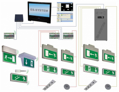
You can find below Emergency Lighting System Installation Method Statement in steps that covers the pre-installation steps and after that installation procedure.
Pre-installation checks for Emergency Lighting System
Ensure the materials, equipment and components are as per approved material submittal and as per technical specification.
Make sure that the emergency lighting drawings are current and marked “Issued for Construction”.
All equipment and components will be installed in strict compliance with each manufacturer’s recommendations.
Ensure the areas are cleared and free from debris, dust & dirt prior to commencing the works.
Materials will be moved to the work site in a safe manner and shall not block access / egress to the site.
Ensure that adequate number of tradesmen and proper tools are available at site.
Inspect the relevant area for any possible clashes with other services.
Sequence of Works for Emergency Lighting System
Ensure all materials, equipment and accessories used have been approved.
Neat workmanship shall be maintained throughout while installing Emergency lighting, equipment and wiring.
Exposed conduits shall be parallel with or at right angles to building line, beams, or ceiling. Symmetrical bends or metal boxes shall be placed at changes in direction or taps.
Where there is false ceiling the cables are directly clipped on the soffit.
For emergency lighting cabling, FP 200 cables will be used.
Before installation, cable will be straightened properly.
When emergency lighting cable passes through walls, floors etc., proper sleeve will be provided.
Where emergency lighting cable passes through floor screeds, bricks walls etc., cable will be installed in sleeves of adequate size to ensure easy withdrawal.
Insulation test will be carried out on emergency lighting cables before termination with 500 V IR Tester.
After the completion of the glanding the cores will be identified and tested.
The network cable screen will be earthed.
It will be ensured that the jacket of the cables at the ends is cut to accommodate the connection to the terminal.
Also make sure that a uniform color coding is used throughout the installation.
All the cables will be secured or tightened well on to the connection terminals to avoid loose connections.
The earth connection points should be clean to provide good electrical conductivity path.

Ensure all maintained and non maintained luminaries are identified and installed in the proper locations and in accordance with the approved shop drawings.
Exit luminaries will be installed along the defined escape routes and will be visible from all points all points of the escape route and luminaries will be placed above each exit door, at each intersection with other escape routes and corridors and near each change of direction as shown in the approved shop drawings.
Special focus will be given to the location of the safety luminaries to cover the specific hazards and to the highlight safety equipment installed.
Intersections with other corridors, changes level, staircases, fire alarm call points and operation equipment and other life safety equipment will be done as shown in the approved shop drawings.
All luminaries with high frequency ballasts will have a built in or separate monitoring facility.
Ensure that the monitoring module is installed and address before the fixing of the luminaries.
Power to the Emergency lighting and central battery panels will be from an essential power source and it will be in accordance with all circuit and cable details as mentioned in the approved LV schematics.
All panels & equipment will be labelled as per approved shop drawings & schematics.
All metallic equipment, accessories & light fittings will be properly earthed.
Circuit details will be provided in the panel board.
The equipment will be fully levelled, aligned and bolted down.
All transit pieces will be removed from the switchboard components where fitted and all components e.g. circuit breakers, relays, contactors, fuse switches interlocks / doors etc. will be hand operated to ensure that their action is free and uninhibited.
All equipment sections / compartments will be thoroughly vacuumed to remove any foreign matter.
Further installation of panels, battery and finalizing like checking of installation dimensions, fastening the panels to the foundation, polarity check, incoming power supply phase sequence check, fixing battery fuse box, cabling of battery and panels etc. to be done under the supervision of the supplier.
Discover more from Electrical Engineering 123
Subscribe to get the latest posts sent to your email.
