
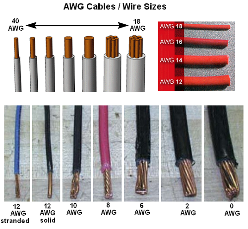
The AWG – American Wire Gauge – is used as a standard method denoting wire diameter, measuring the diameter of the conductor (the bare wire) with the insulation removed.
AWG is sometimes also known as Brown and Sharpe (B&S) Wire Gauge.
The AWG table below is for a single, solid, round conductor.
Because of the small gaps between the strands in a stranded wire, a stranded wire with the same current-carrying capacity and electrical resistance as a solid wire, always have a slightly larger overall diameter.
The higher the number – the thinner the wire.
Typical household wiring is AWG number 12 or 14.
Telephone wire is typical AWG 22, 24, or 26.
The table below indicates the current ratings of PVC-insulated single and multicore wiring cables.
Be aware that the current load depends on installation method – the enclosure – and how well the resistance heat is removed from the cable.
Operating temperature of the conductor, ambient temperature and type of conductor insulation is important.
Always check the manufactures data before detailed engineering.
| AWG | Diameter (mm) |
Diameter (in) |
Square (mm2) |
Resistance Copper (ohms/1000m) (Ohms/1000 ft) |
Typical Max. Current Load Ratings – Copper (amps)1) | |||||
|---|---|---|---|---|---|---|---|---|---|---|
| Single Core | Multicore | |||||||||
| up to 3 cores | 4 – 6 cores | 7 – 24 cores | 25 – 42 cores | 43 and above | ||||||
| 40 | 0.08 | . | 0.0050 | 3420 | ||||||
| 39 | 0.09 | . | 0.0064 | 2700 | ||||||
| 38 | 0.10 | 0.0040 | 0.0078 | 2190 | ||||||
| 37 | 0.11 | 0.0045 | 0.0095 | 1810 | ||||||
| 36 | 0.13 | 0.0050 | 0.013 | 1300 | ||||||
| 35 | 0.14 | 0.0056 | 0.015 | 1120 | ||||||
| 34 | 0.16 | 0.0063 | 0.020 | 844 | ||||||
| 33 | 0.18 | 0.0071 | 0.026 | 676 | ||||||
| 32 | 0.20 | 0.0080 | 0.031 | 547 | ||||||
| 30 | 0.25 | 0.010 | 0.049 | 351 | ||||||
| 28 | 0.33 | 0.013 | 0.080 | 232 | ||||||
| 27 | 0.36 | 0.014 | 0.096 | 178 | ||||||
| 26 | 0.41 | 0.016 | 0.13 | 137 | ||||||
| 25 | 0.45 | 0.018 | 0.16 | 108 | ||||||
| 24 | 0.51 | 0.020 | 0.20 | 88 | 3.5 | 2 | 1.6 | 1.4 | 1.2 | 1.0 |
| 22 | 0.64 | 0.025 | 0.33 | 52 | 5.0 | 3 | 2.4 | 2.1 | 1.8 | 1.5 |
| 20 | 0.81 | 0.032 | 0.50 | 34 | 6.0 | 5 | 4.0 | 3.5 | 3.0 | 2.5 |
| 18 | 1.0 | 0.040 | 0.82 | 22 | 9.5 | 7 | 5.6 | 4.9 | 4.2 | 3.5 |
| 16 | 1.3 | 0.051 | 1.3 | 13 | 20 | 10 | 8.0 | 7.0 | 6.0 | 5.0 |
| 14 | 1.6 | 0.064 | 2.1 | 8.5 | 24 | 15 | 12 | 10 | 9.0 | 7.5 |
| 13 | 1.8 | 0.072 | 2.6 | 6.8 | ||||||
| 12 | 2.1 | 0.081 | 3.3 | 5.4 | 34 | 20 | 16 | 14 | 12 | 10 |
| 10 | 2.6 | 0.10 | 5.3 | 3.4 | 52 | 30 | 24 | 21 | 18 | 15 |
| 8 | 3.3 | 0.13 | 8.3 | 2.2 | 75 | 40 | 32 | 28 | 24 | 20 |
| 6 | 4.1 | 0.17 | 13.3 | 1.5 | 95 | 55 | 44 | 38 | 33 | 27 |
| 4 | 5.2 | 0.20 | 21.2 | 0.80 | 120 | 70 | 56 | 49 | 42 | 35 |
| 3 | 26.7 | 154 | 80 | 64 | 56 | 48 | 40 | |||
| 2 | 6.5 | 0.26 | 33.6 | 0.50 | 170 | 95 | 76 | 66 | 57 | 57 |
| 1 | 7.4 | 0.29 | 42.4 | 0.40 | 180 | 110 | 88 | 77 | 66 | 55 |
| 0 (1/0) | 8.3 | 0.33 | 53.5 | 0.31 | 200 | |||||
| 00 (2/0) | 9.3 | 0.37 | 67.4 | 0.25 | 225 | |||||
| 000 (3/0) | 10.4 | 0.41 | 85.0 | 0.20 | 275 | |||||
| 0000 (4/0) | 11.7 | 0.46 | 107 | 0.16 | 325 | |||||
| 250 | 127 | 345 | ||||||||
| 300 | 152 | 390 | ||||||||
| 400 | 178 | 415 | ||||||||
1) Current ratings for up to 1000 V, PVC-insulated single and multicore wiring cables, ambient temperature up to 30oC
The higher the gauge number, the smaller the diameter, and the thinner the wire.
Because of less electrical resistance a thicker wire carries more current with less voltage drop than a thinner wire.
For longer distances it may be necessary to increase wire diameter – reducing the gauge – to limit voltage drop.
Correction-factors at ambient temperature above 30oC
- ambient temperature 31 – 40 oC: correction factor = 0.82
- ambient temperature 41 – 45 oC: correction factor = 0.71
- ambient temperature 45 – 50 oC: correction factor = 0.58
American Wire Gauge Conductor Size Table
American wire gauge (AWG) is a standardized wire gauge system for the diameters of round, solid, nonferrous, electrically conducting wire.
The larger the AWG number or wire gauge, the smaller the physical size of the wire.
Smallest AWG size is 40 and the largest is 0000 (4/0).
AWG general rules of thumb – for every 6 gauge decrease, the wire diameter doubles and for every 3 gauge decrease, the cross sectional area doubles.
Note – W&M Wire Gauge, US Steel Wire Gauge and Music Wire Gauge are different systems.
American Wire Gauge (AWG) Sizes and Properties Chart / Table
Table 1 lists the AWG sizes for electrical cables / conductors.
In addition to wire size, the table provides values load (current) carrying capacity, resistance and skin effects.
The resistances and skin depth noted are for copper conductors.
A detailed description of each conductor property is described below Table 1.
Table 1: American Wire Gauge (AWG) Cable / Conductor Sizes and Properties
| AWG | Diameter [inches] |
Diameter [mm] |
Area [mm2] |
Resistance [Ohms / 1000 ft] |
Resistance [Ohms / km] |
Max Current [Amperes] |
Max Frequency for 100% skin depth |
| 0000 (4/0) | 0.46 | 11.684 | 107 | 0.049 | 0.16072 | 302 | 125 Hz |
| 000 (3/0) | 0.4096 | 10.40384 | 85 | 0.0618 | 0.202704 | 239 | 160 Hz |
| 00 (2/0) | 0.3648 | 9.26592 | 67.4 | 0.0779 | 0.255512 | 190 | 200 Hz |
| 0 (1/0) | 0.3249 | 8.25246 | 53.5 | 0.0983 | 0.322424 | 150 | 250 Hz |
| 1 | 0.2893 | 7.34822 | 42.4 | 0.1239 | 0.406392 | 119 | 325 Hz |
| 2 | 0.2576 | 6.54304 | 33.6 | 0.1563 | 0.512664 | 94 | 410 Hz |
| 3 | 0.2294 | 5.82676 | 26.7 | 0.197 | 0.64616 | 75 | 500 Hz |
| 4 | 0.2043 | 5.18922 | 21.2 | 0.2485 | 0.81508 | 60 | 650 Hz |
| 5 | 0.1819 | 4.62026 | 16.8 | 0.3133 | 1.027624 | 47 | 810 Hz |
| 6 | 0.162 | 4.1148 | 13.3 | 0.3951 | 1.295928 | 37 | 1100 Hz |
| 7 | 0.1443 | 3.66522 | 10.5 | 0.4982 | 1.634096 | 30 | 1300 Hz |
| 8 | 0.1285 | 3.2639 | 8.37 | 0.6282 | 2.060496 | 24 | 1650 Hz |
| 9 | 0.1144 | 2.90576 | 6.63 | 0.7921 | 2.598088 | 19 | 2050 Hz |
| 10 | 0.1019 | 2.58826 | 5.26 | 0.9989 | 3.276392 | 15 | 2600 Hz |
| 11 | 0.0907 | 2.30378 | 4.17 | 1.26 | 4.1328 | 12 | 3200 Hz |
| 12 | 0.0808 | 2.05232 | 3.31 | 1.588 | 5.20864 | 9.3 | 4150 Hz |
| 13 | 0.072 | 1.8288 | 2.62 | 2.003 | 6.56984 | 7.4 | 5300 Hz |
| 14 | 0.0641 | 1.62814 | 2.08 | 2.525 | 8.282 | 5.9 | 6700 Hz |
| 15 | 0.0571 | 1.45034 | 1.65 | 3.184 | 10.44352 | 4.7 | 8250 Hz |
| 16 | 0.0508 | 1.29032 | 1.31 | 4.016 | 13.17248 | 3.7 | 11 k Hz |
| 17 | 0.0453 | 1.15062 | 1.04 | 5.064 | 16.60992 | 2.9 | 13 k Hz |
| 18 | 0.0403 | 1.02362 | 0.823 | 6.385 | 20.9428 | 2.3 | 17 kHz |
| 19 | 0.0359 | 0.91186 | 0.653 | 8.051 | 26.40728 | 1.8 | 21 kHz |
| 20 | 0.032 | 0.8128 | 0.518 | 10.15 | 33.292 | 1.5 | 27 kHz |
| 21 | 0.0285 | 0.7239 | 0.41 | 12.8 | 41.984 | 1.2 | 33 kHz |
| 22 | 0.0254 | 0.64516 | 0.326 | 16.14 | 52.9392 | 0.92 | 42 kHz |
| 23 | 0.0226 | 0.57404 | 0.258 | 20.36 | 66.7808 | 0.729 | 53 kHz |
| 24 | 0.0201 | 0.51054 | 0.205 | 25.67 | 84.1976 | 0.577 | 68 kHz |
| 25 | 0.0179 | 0.45466 | 0.162 | 32.37 | 106.1736 | 0.457 | 85 kHz |
| 26 | 0.0159 | 0.40386 | 0.129 | 40.81 | 133.8568 | 0.361 | 107 kHz |
| 27 | 0.0142 | 0.36068 | 0.102 | 51.47 | 168.8216 | 0.288 | 130 kHz |
| 28 | 0.0126 | 0.32004 | 0.081 | 64.9 | 212.872 | 0.226 | 170 kHz |
| 29 | 0.0113 | 0.28702 | 0.0642 | 81.83 | 268.4024 | 0.182 | 210 kHz |
| 30 | 0.01 | 0.254 | 0.0509 | 103.2 | 338.496 | 0.142 | 270 kHz |
| 31 | 0.0089 | 0.22606 | 0.0404 | 130.1 | 426.728 | 0.113 | 340 kHz |
| 32 | 0.008 | 0.2032 | 0.032 | 164.1 | 538.248 | 0.091 | 430 kHz |
| 33 | 0.0071 | 0.18034 | 0.0254 | 206.9 | 678.632 | 0.072 | 540 kHz |
| 34 | 0.0063 | 0.16002 | 0.0201 | 260.9 | 855.752 | 0.056 | 690 kHz |
| 35 | 0.0056 | 0.14224 | 0.016 | 329 | 1079.12 | 0.044 | 870 kHz |
| 36 | 0.005 | 0.127 | 0.0127 | 414.8 | 1360 | 0.035 | 1100 kHz |
| 37 | 0.0045 | 0.1143 | 0.01 | 523.1 | 1715 | 0.0289 | 1350 kHz |
| 38 | 0.004 | 0.1016 | 0.00797 | 659.6 | 2163 | 0.0228 | 1750 kHz |
| 39 | 0.0035 | 0.0889 | 0.00632 | 831.8 | 2728 | 0.0175 | 2250 kHz |
| 40 | 0.0031 | 0.07874 | 0.00501 | 1049 | 3440 | 0.0137 | 2900 kHz |
AWG Notes: American Wire Gauge (AWG) is a standardized wire gauge system used predominantly in the United States to note the diameter of electrically conducting wire.
The general rule of thumb is for every 6 gauge decrease the wire diameter doubles and every 3 gauge decrease doubles the cross sectional area.
Diameter Notes: A mil is a unit of length equal to 0.001 inch (a “milli-inch” or a “thousandth of one inch”) ie. 1 mil = 0.001″.
Resistance Notes:
The resistance noted in the table above is for copper wire conductor.
For a given current, you can use the noted resistance and apply Ohms Law to calculate the voltage drop across the conductor.
Current (ampacity) Notes:
The current ratings shown in the table are for power transmission and have been determined using the rule of 1 amp per 700 circular mils, which is a very conservative rating.
For reference, the National Electrical Code (NEC) notes the following ampacity for copper wire at 30 Celsius:
14 AWG – maximum of 20 Amps in free air, maximum of 15 Amps as part of a 3 conductor cable;
12 AWG – maximum of 25 Amps in free air, maximum of 20 Amps as part of a 3 conductor cable;
10 AWG – maximum of 40 Amps in free air, maximum of 30 Amps as part of a 3 conductor cable.
Check your local electrical code for the correct current capacity (ampacity) for mains and in wall wiring.
Skin Effect and Skin Depth Notes:
Skin effect is the tendency of an alternating electric current (AC) to distribute itself within a conductor so that the current density near the surface of the conductor is greater than that at its core.
That is, the electric current tends to flow at the “skin” of the conductor.
The skin effect causes the effective resistance of the conductor to increase with the frequency of the current.
Maximum frequency show is for 100% skin depth (ie. no skin effects).
American Wire Gauge (AWG) Wire Sizes
Sharing is caring:

Discover more from Electrical Engineering 123
Subscribe to get the latest posts sent to your email.