Fiber Optic cable is made up of thin fibers which are useful for the transmission of large amount of data. Infact the optical fiber is a hair thin cylindrical fiber of glass or any transparent dielectric medium. The fiber which are used for optical communication are wave guides made of transparent dielectrics. Its function is to guide visible and infrared light over long distances.
Fiber optic (or “optical fiber”) refers to the medium and the technology associated with the transmission of information as light impulses along a glass or plastic wire or fiber. Fiber optic wire carries much more information than conventional copper wire. Long distance communication lines are now fiber optic all over the world. Optical fibers use light to send information through the optical medium.
Due to evolution of optical fiber technology over few years it has now become the only choice for providing broadband internet services even at the end user level and now at home levels FO cables are laid by telecom companies. Thanks to optical fiber technology so that we are able to get high speed internet and high definition TV at our homes and offices.
Fiber Optics cables are useful for wider range of application in almost all fields like telecommunication, fiber optic internet, space, fibre optic broadband networks, computers, medical and military applications etc.
Fiber Optic Working Principle
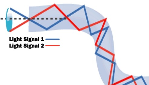
The function of FO cable is based on the concept of total internal reflection. When a ray of light travels from a denser to a rarer medium such that the angle of incidence is greater than the critical angle, the ray reflects back into the same medium this phenomena is total internal reflection. In the optical fiber the rays undergo repeated total number of reflections until it emerges out of the other end of the fiber, even if the fiber is bent.

Based upon this principle we can send as many as we want different light signals that will go at different angles and there will be no crossing or loss of data because each light wave will have its own path. Hence fiber optik can transfer huge data simultaneously like different channels.
Structure of Fiber Optics
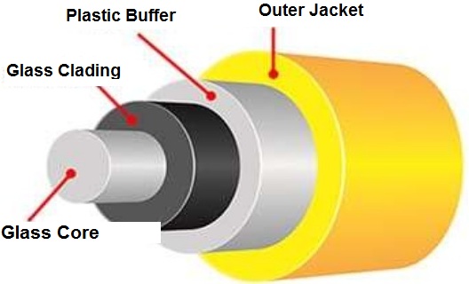
In original the fiber optic material was very much fragile and can break easily. Therefore in order to make its handling easy some impurities are mixed and it is now easy to handle fiber optics. Now you can handle fiber optic like a plastic wire. The structure of optical fiber consists of below mentioned parts:

Glass Core:
This is the central tube that transfers the data, this core is of very thin size and consists of optically transparent dielectric medium and carries the light form transmitter to receiver. The core diameter can vary from about 5 micron to 100 micron.
Glass Cladding:
This is outer optical material surrounding the core having reflecting index lower than the glass core. The glass cladding is also major component of fiber optic technology because it helps to keep the light within the core throughout the phenomena of total internal reflection.
Plastic Buffer Coating:
Plastic coating that protects the fiber made of silicon rubber. The typical diameter of fiber after coating is 250-300 um.
Outer Jacket:
Optical fiber cables come in number of cores that can start from single core to hundreds or thousands of cores. In order to handle these cores these are arranged in bundles in optical cables. These bundles are protected by the cable’s outer covering which is known as fiber optic jacket. The outer jacket also protects the FO cores from weathering effect and also from heat and fire as per its application.
In addition there is also provision of metallic wire inside the multi-core optical cables that help during installation and pulling of fiber optic cables that prevents the damage to internal FO core.
Transfer Modes Of Fiber Optic Cable
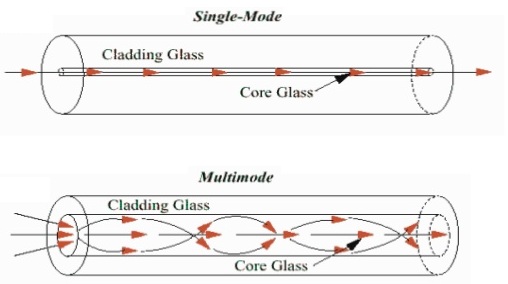
Optical Fiber cables can transfer the data in two modes i.e. single mode & multi mode. Both modes have its own pros and cons.
A single mode optical cable is a single stand of glass fiber with a diameter of 8.3 to 10 microns that has one mode of transmission. Single-mode fiber gives you a higher transmission rate and up to 50 times more distance than multimode, but it also costs more. Single-mode fiber has a much smaller core than multimode because it needs to transfer single signal at one time.
On the other hand multi mode optical cable consists of multiple glass fibers, with common diameters in the 50-to-100 micron range. Multimode fiber provides high bandwidth at high speeds over medium distances. However, in long cable runs (greater than 3000 feet), multiple paths of light can cause signal distortion at the receiving end, resulting in an unclear and incomplete data transmission. Therefore for long distances this mode is not much useful.
How Fiber Optics is made?
There are basically three steps in the manufacturing process of the Fiber Optics, which include:
- Making a Preform Glass Cylinder
- Drawing the Fiber’s from the preform
- Testing the Fiber
Advantages of Fiber Optic Cables
- Long life as compared to copper wire.
- Easy handling and installation.
- Signals are secure and not detectable by detectors.
- No or minimum electromagnetic interference
- Attenuation or loss of signals in Fiber Optics is lower than coaxial cable or twisted pair.
- No protection needed against grounding and any other voltage problems.
Disadvantage of FO Cables
- Maintenance requires high skills and special training of staff.
- Point to point working is possible only.
- Requires precise and costly instruments
- Jointing and splicing is time consuming jobs.
Evolution of Fiber Optics Technology
- 1880 – Alexander Graham Bell
- 1930 – Patents on tubing
- 1960 – Laser first used as light source
- 1965 – High loss of light discovered
- 1970s – Refining of manufacturing process
- 1980s – OF technology becomes backbone of long distance telephone networks in NA.
Standard optical fiber cables
The following summarizes the current state-of-the-art research using standard telecoms-grade single-mode, single-solid-core fibre cables.
| Year | Organization | Effective speed | WDM channels | Per channel speed | Distance |
|---|---|---|---|---|---|
| 2009 | Alcatel-Lucent | 15.5 Tbit/s | 155 | 100 Gbit/s | 7000 km |
| 2010 | NTT | 69.1 Tbit/s | 432 | 171 Gbit/s | 240 km |
| 2011 | NEC | 101.7 Tbit/s | 370 | 273 Gbit/s | 165 km |
| 2011 | KIT | 26 Tbit/s | >300 | 50 km | |
| 2016 | BT & Huawei | 5.6 Tbit/s | 28 | 200Gb/s | circa 140 km ? |
| 2016 | Nokia Bell Labs, Deutsche Telekom T-Labs & Technical University of Munich | 1 Tbit/s | 1 | 1Tb/s | |
| 2016 | Nokia-Alcatel-Lucent | 65 Tbit/s | 6600 Km | ||
| 2017 | BT & Huawei | 11.2 Tbit/s | 28 | 400 Gb/s | 250 Km |
The 2016 Nokia/DT/TUM result is notable as it is the first result that pushes close to the Shannon theoretical limit.
Discover more from Electrical Engineering 123
Subscribe to get the latest posts sent to your email.
