Below is given the method statement for performing the installation of optical fiber cabling system for a project. The method is given from receiving the material on the installation site and what to do after that.
Make sure that for all drawings and schedules necessary approvals are available.
Offloading and handling of Fiber Optic cable
- Adequate protection shall be provided to prevent mechanical damage during off-loading.
- Ensure that the lifting equipment is adequately rated for the specified weight (shown on the rating plate) and fit for purpose.
- Off-loading of the Fiber Optic cable shall be made in open area and the equipment shall be protected against external elements, damage or misuse.
- Verify that the bracing & supports are provided to prevent damage during transit, lifting or unloading.
- Use only the fixtures provided (transport eyebolts, bugles, lifting points) while lifting or pulling the cable drums.
- Lifting, pulling or pushing shall not be done manual.
- Lifting and pulling of the cable drums shall be as per the manufacture recommendation.
- Use only lifting slings of sufficient length to obtain an angle of 45° between the cable drums.
- The cable drums shall be offloaded at an open area in an upright position.
- Avoid standing directly underneath the cable drums, when lifted, unless absolutely necessary.
- The storage base must be smooth and as horizontal as possible.
- Lower the cable drums slowly and place it gently on the ground.
Procedure of Conduit / Duct Installation
100mm Pipes are laid with due regard to the fall and invert levels set out ( using the concrete blocks ) in the shop drawing..
No protective cap, disc or other appliance on the end of pipe or fitting shall be removed permanently until the pipe or fitting which it protects is about to be jointed. Pipes and fittings shall be examined for damage and the joint surfaces and components shall be cleaned.
Suitable measures shall be taken to prevent soil or other material from entering pipes, and to anchor each pipe to prevent flotation or other movement before the works are complete.
Before making the joint ensures that both the pipe end and the sealing ring are clean. Lubricate both the pipe ends and the sealing ring in the socket with silicone lubricant.
Ensure that components to be joined (by push-fit method) are correctly aligned, and then push the spigot fully into the socket.
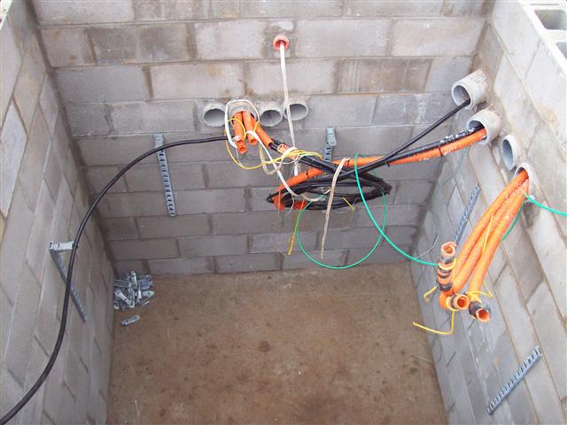
Every 200Meter manhole shall be provided for pulling the Fiber optic Cable and every 90 deg deviation right angle manhole shall be provided. Manhole shall be provided at every splicing location or at every 800m. The dimension of the splicing pit shall be as per the standard i.e 1000x1000x1000MM from inside.
Where the splicing pit/manhole installed the distance between power cable and manhole shall be 200mm.

Installation Of Optical Fiber Cables
Pre-installation inspection of cables for continuity & insulation resistance will be carried out as per requirement and recorded.
All the cable rollers shall be of sufficient size to accommodate the cable without any damage of its outer sheath.
All the cable rollers shall be of sufficient size to accommodate the cable without any damage of its outer sheath.
The cables shall be laid in a sequenced manner. The cable shall leave from bottom of the drum while pulling. The pulling tension does not exceed the safe pulling tension of allowable force of the cable. The winch rope will be pulled into the trench from the winch position to the cable position using the draw rope. Check that the wire-pulling sock will be fitted to the cable end and the winch rope will be attached to the sock eye.
Lubricate the cable, if necessary from the drum end prior to its entry into the trench with the approved pulling compound.
After cable pulling is completed and testing has done, inspection to proceed for cable laying, cable tiles and back-filling.
As per approved shop drawing warning tape shall be provided 300mm below the ground level along the cable route.
Identify the cable route by placing the concrete cable route marker of at 30 meters of interval to the straight run and at points where the route changes direction to entire route for cables.
Proper care shall be taken while pulling the cables through sleeves to avoid damages.
Additional FOC loop i.e 15-20 meter shall be left coiled on the wall of the manhole/pit, using the Gl brackets.
Connect the strength member of the cable to the pull line. Unless cables are designed for such use, basket grips and similar methods of attachment should not be used.
UL approved lubricant shall be used to assist in pulling fiber optic cable.
Use a swivel while pulling to prevent the cable from being twisted by rigid attachment to a fish tape. To keep pulling tension within careful limits, do not use power pullers with fibre, unless you use a tension meter as well. As a general rule, the tension should not exceed 300 pounds with indoor cables and 600 pounds with outdoor cables. But always check the specifications for the cable to be sure.
Use lots of large pull boxes and divide pulls in half or even thirds at corners or pull boxes. A pulling operation must be stopped if pulling tensions reach the cable’s limit.
The discontinued pull will have to be aborted, the cable pulled back out and replaced on the reel, and the pull started again using shorter runs, better lubrication, or both. The cable may be reused if the pull or extraction has not damaged it.
Identify exact terminating locations in advance, keeping in mind that the cable must be pulled all the way to where it will be terminated, not just into the room. This obvious though often overlooked step can lead to costly mistakes if forgotten.
Carefully measure the cable’s path before the conduit pull to avoid the need for splices. Not only do splices cost time and money, but they also cause loss in both signal quality and strength. In fact, most designers specify point to-point or device-to-device runs to avoid needless signal loss from splices.

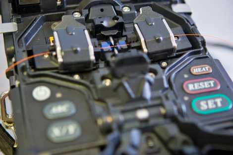
Optical fiber splicing machine in process
The preferred way to measure is to use a pull tape. This product, sometimes called mule tape, is a flat ribbon, consecutively numbered in feet, which is usually made of polyester or aramid yarn and may be coated with plastic for waterproofing. It comes in different lengths and pull strengths.
Pull the pull tape into the conduit, or along the cable path, for an initial measurement, and add to that extra length for splices, terminations, and future access coils, if specified. The amount of additional optical fiber cable needed for splicing depends on site conditions, splicing method used, and long-range plans for cable usage. For termination length, figure on about 2 to 3 meters of additional cable beyond where the terminal will be mounted. And add about 10 to 12 meters per span for any access or repair coils. A good rule of thumb to cover all these additional cable lengths is to allow 1 percent extra for outside plant (outdoor) cable runs and 5 to 7 percent extra for inside cable runs.
Choose crews based on the length of the pull, total degrees of bend, tail loading (force required to pull cable off feed reel), use of lubricant, and use of power putting equipment. In most cases, two- or three-person crews are ideal. That way, one person pays the cable off the reel and into the duct, while one or two others pull at the other end.
Don’t forget to mark the cable with a marker tape buried below the surface; this will act as a warning to anyone digging in the area. If you’re using a cable construction not containing metal, use a metal impregnated marking tape so the cable can be located with appropriate equipment.
Aside from the regular work hazards of cuts, bruises, falls, etc., you must consider additional hazards. Check for hazardous gases before anyone enters a manhole. In fact, you might need a separate air supply. You’ll have considerable forces on the puller, sheaves, and/or pulleys. And, you may be using pulleys 5 ft in dia. If one of these lets go, serious injury can result. Your best bet is to use chain or steel cable (chokers) rather than rope to tie pulleys and pulling equipment in place. Above all else: Examine each situation carefully before you start work.
Guard the manhole A combination guard and emergency man lift is ideal. If the manhole is in a high traffic area, you’ll need a warning light. If the cable installation takes more than one day and you leave it idle overnight, protect it during that time.
The optical fiber cable is valuable enough, along with the labor invested in installation that it might pay to hire someone to guard the cable form damage or theft during off hours.
Discover more from Electrical Engineering 123
Subscribe to get the latest posts sent to your email.


How to download Fiber optic cable installation method of statement
You can find Optical Fiber covered in structured cabling system.