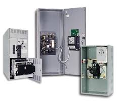
The purpose of this method statement is to define the sequence and methodology for the installations of Automatic Transfer Switches and bypass-isolation switch ATS & BPS.
Prior to commencement of work, shop drawing will be processed and submitted for approval by the Engineer.
Shop drawing will include front and side views of enclosure, Overall dimensions, components identity, components type and ratings, electrical characteristics, incoming and outgoing pipe location among others.
Only approved shop drawing will be used for installation and any changes in site installation as approved by the consulting engineer will be reflected on as-built.
All materials and product to be used will be submitted for approval by the Engineer in form of material submittal or product data.
Only approved materials and product from approved manufacturer will be used for installation.
Below mentioned tools and equipment shall be arranged:
- Electrician hand tools
- Helper’s tool box
- Hole puncher
- Electric drill, Cutter
- Cordless screw gun
- Round file reamer
- Hydraulic pulley
- Torque wrench
- Megger Tester
- Multi-meter
ATS Installation Procedure
Installation will be carried out in accordance to contract specifications and approved drawings.
Automatic transfer switch installation will be carried out by skilled and suitably experienced electricians under supervision of highly competent site supervisors and engineers to ensure the correctness and quality of installation.
ATS/BPS equipment will be UL listed in accordance with UL-1008 and will be same manufacturer as the Synchronizing Switchgear manufacturer.
ATS/BPS and its components ratings will be as per the approved shop drawings and load calculations.
Prior to dispatch of ATS equipment, a mandated factory test must have been taken placed, witness by the engineer and contractor apart from site testing in the premises of the manufacturer.
ATS equipment will be delivered in site in complete system including its internal & external components such as double throw power transfer switch mechanism and microprocessor controller.
The delivered equipment will conform to approved shop drawings and engineer’s requirement.
Hook will be used on top to unload the equipment.
Location/foundation of ATS/BPS would have been approved prior to erection of equipment.
ATS will be unloaded and bolted to the approved Leveling will be observed.
Clearances and distances from the wall will be as per the approved shop drawing and applicable regulation.
An approved containment will be provided to accommodate cables terminating to ATS and connecting to synchronizing switch-gear and generator sets.
Correct cable tie will be used for proper cable dressing.
Proper cutting and glanding plate will be provided for incoming and outgoing cable access.
Control and monitoring wiring will be connected to the transfer switches, synchronizing switch gear and generator sets as per the approved drawing.
Necessary requirement will be coordinated with synchronizing switchgear.
Cable tags and identification ferrule will be provided to cables.
Earthing cable will have pg glands and correct cable ties will be used to arrange the cables.
ATS equipment will be properly earthed and bonded to grounding system.
ATS/BPS manufacturer will coordinate all necessary requirements with the engine/generator manufacturer.
Using torque wrench, tightness of termination will be ensured in preparation to torque test.
Label or identification nameplate will be provided for equipment identification.
Cleaning will be employed in preparation of testing and inspection.
Upon completion of installation and termination, testing and commissioning of the equipment will be carried out by the manufacturer to be witness by the consultant.
Inspection Request will be formally raised to the engineer to ensure accuracy and quality of works.
Discover more from Electrical Engineering 123
Subscribe to get the latest posts sent to your email.
