
What is a balun?
A Balun is special type of transformer that performs two functions i.e. impedance transformation and balanced to unbalanced transformation. The term balun is a contraction of “balanced to unbalanced transformer”
Why do we need a balun?
Baluns are important because many types of antennas (dipoles, yagis, loops) are balanced loads, which are fed with an unbalanced transmission line (coax). Baluns are required for proper connection of parallel line to a transceiver with a 50 ohm unbalanced output.
The antenna’s radiation pattern changes if the currents in the driven element of a balanced antenna are not equal and opposite. Baluns prevent unwanted RF currents from flowing in the “third” conductor of a coaxial cable.
Balanced vs Unbalanced Transmission Lines
A balanced transmission line is one whose currents are symmetric with respect to ground so that all current flows through the transmission line and the load and none through ground. Note that line balance depends on the current through the line, not the voltage across the line.
An example of Balanced Line
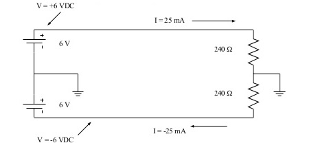
Here is an example of a balanced line. DC rather than AC is used to simplify the analysis. Notice that the currents are equal and opposite and the that the total current flowing through ground = 25mA-25mA = 0
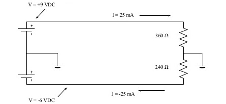
Below is another example, note that the total current flowing through ground is again 0. Because the ground current is 0, the ground is not required.
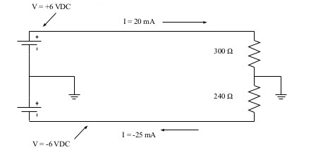
Below is another example. Is the line balanced? No – although the voltages are equal and opposite, the currents are not!
What is Voltage Balun
A Voltage Balun is one whose output voltages are equal and opposite (balanced with respect to ground). True balance occurs only if the balun’s load is symmetric with respect to ground. Voltages baluns are easily constructed and commonly used in spite of their inability to provide true current balance.
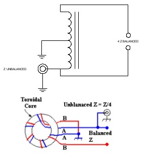
4:1 Voltage Balun
This is the simplest voltage balun, consisting of two coils of wire connected as shown below. The coils may use an air core or a ferrite core. Current flowing through the lower coil induces an equal and opposite voltage in the upper coil. The primary circuit contains N turns and the secondary 2N, so the input impedance is ZL(N/2N)2= ¼ ZL
4:1 Transmission Line Voltage Balun
This voltage balun is constructed solely for transmission line and requires two cores. Unlike the transformer- type baluns, this balun may be used only over a narrow range of frequencies. The extra half wave section causes the voltage at its output to be equal and opposite to the voltage at the input.
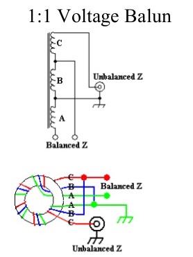
1:1 Voltage Balun
This voltage balun is similar to the 4:1, but uses 3 windings connected in series. The coils may use an air core or a ferrite core. Current flowing through the lower coil induces an equal and opposite voltage in the upper coil. The primary circuit contains N turns and the secondary N, so the input impedance is ZL(N/N)2= ZL;
Current Baluns
A Current Balun is one whose output currents are equal and opposite (balanced with respect to ground). With the exception of the 1:1 current balun, current baluns are more expensive to construct than voltage baluns and thus are less widely used. Current baluns may be made with RF transformers on ferrite cores or with lengths of transmission line.
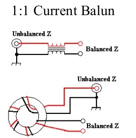
1:1 Current Balun
This is the simplest current balun, consisting of two coils of wire connected as shown below. The coils may use an air core or a ferrite core. Often a current balun is made by winding coaxial cable into a coil, with or without a ferrite core. The load impedance is not changed by the balun. The inductive reactance of the windings prevents common mode currents from flowing and ensures a balanced output. The inductive reactance should be 10 times the load impedance at the lowest frequency of operation
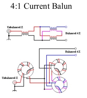
4:1 Current Balun
6 windings on 3 cores are required to construct a 4:1 current balun. This balun consists of a 1:1 balun followed by a 4:1 balanced-to- balanced current transformer. The windings on the 1:1 balun should have at least an inductive reactance at least 10 times greater than the input impedance. The windings on the 4:1 current transformer should have an inductive reactance at least 10 times greater than the output impedance (40 times Zin)
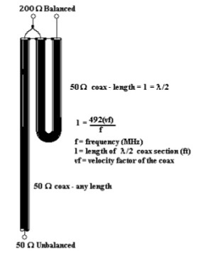
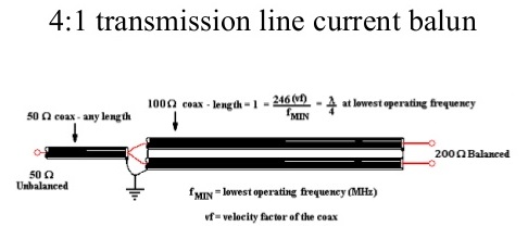
4:1 transmission line current balun
Only transmission line is needed to construct this current balun. The two lengths of transmission line that comprise the balun need to have a characteristic impedance of ~ 100 ohms. RG-62 (Z = 95 ohms) works very well. The length of the two sections of 100 ohm coax must be at least ¼ wavelength at the lowest frequency (approx 47 feet at 3.5 MHz) and a this type of balun should work over a 8 to 1 frequency range. This type of balun is often used at higher frequencies where ferrite cores are lossy and short lengths of coax are required.
Construction of Baluns
Transformer Baluns use solid wire, preferably enameled, for the windings. For transmitting applications the wire should be #14 or larger. A 1.5 inch diameter ferrite/powdered iron core is sufficient for powers to 100 W. For QRO operation, use a 2.5 – 3 inch diameter core. Select the proper core material for the desired frequencies of operation, For HF baluns, 6 – 8 turns of wire around a toroidal core is sufficient. Air core baluns will need 10 – 20 turns.
In the case of transmission line baluns. coiling the coax sections improves common-mode rejection.
Use of Balun in TV Antenna
An old typical usage of the balun was (and still is) with TV antennas. The folded dipole is part of a yagi antenna which looks something like a pole with rods set across it at right angles. The second last one is folded into an oblong or rectangular shape. A folded dipole exhibits two important characteristics (a) its bandwidth is good for over an octave (e.g. 50 Mhz to 100 Mhz or say 120 Mhz to 240 Mhz) AND its characteristic impedance is a more or less a constant 300 ohms.
In earlier days extensive use was made of 300 ohm twin lead ribbon cable to feed the signals to the TV receiver. BTW you can use just a length of 300 ohm ribbon cable to make a folded dipole.
When colour (or color if you prefer) TV was introduced the ribbon cable often created problems which could be rectified by the use of co-axial cable. This is not strictly correct because coax had earlier uses in TV because of other problems such as ghosting which became intolerable with the introduction of colour.
Now 300 ohm coax can be and is made. However 50 and 75 ohm cable is preferred for a variety of reasons. Our folded dipole also exhibits a “balanced” feed characteristic whilst coaxial cable has an “unbalanced” characteristic. Two problems. Each solved by the use of the balun.
Perhaps we should have some clarification about this balanced versus unbalanced jazz. Mentally visualise it this way. If we have a plus 12V D.C. supply with ground return. That could be regarded for our illustrative purposes as the unbalanced 75 ohm input. On the other hand we could have a symmetrical power supply referenced to ground which provides a + 12V D.C. AND a – 12V D.C. voltage. The only difference is we are dealing with R.F. which of course is very high A.C.
A practical 300 / 75 ohm balun would consist of four pieces of 0.4mm wire wound 2 1/2 turns through a balun core (look a bit like binoculars). In so doing we have achieved our two goals,
(a) the impedance transformation and
(b) gone from unbalanced to balanced.
Sharing is caring:

Discover more from Electrical Engineering 123
Subscribe to get the latest posts sent to your email.