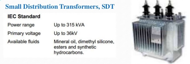
In general understanding electrical distribution transformers are used to reduce primary system voltages (which is normally 2.4-34.5kV) to the level of utilization voltages i.e. 120- 600V.
International electrotechnical commission standards do not distinguish between distribution electrical transformers and power transformer.
They are all power electrical transformers in the sense that their purpose is to transmit power from one voltage level to another level.
Traditionally or most commonly known transformers which are used to transform the high voltage down to the value of domestic consumer voltage (usually 400V or less) are called distribution transformers.
Common for most electrical transformers regardless of size and application is the basic physics and the dominant materials, like Special types of thin magnetic steel plates in the core, which provides the necessary strong magnetic field because of the unique magnetic properties of iron, copper or aluminum as conductor materials in the electrical transformers windings.
Also cellulose products like high density paper and press-board as solid insulation materials has been and with few exceptions still is dominant. Another component or part of the transformer is mineral oil which is used as insulating fluid plus providing the cooling function in a transformer.
Basic Types Of Transformers
In practical transformer design the manufacturer has the choice between two different basic concepts.
- Core type transformer
- Shell type transformer
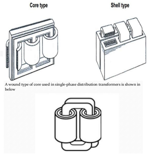
In a nutshell we can say that while the winding of core –type enclose the core, the core of shell-type encloses the winding.
Looking at the active part (i-e the core with the winding) of a core type, the winding are well visible, but they hide the core limbs.
Only the upper and lower yoke of the core are visible.
Looking at the active part (i-e the core with the winding) of a core type, the winding are well visible, but they hide the core limbs.
Only the upper and lower yoke of the core are visible. In shell-type the core hides the major part of the winding.
Another difference is that the axis of the core-type winding is normally vertical while it can be horizontal or vertical in shell- type. Now a days core-type electrical transformers are given preference over shell-type electrical transformers.

Common Types of Distribution electrical transformers
There are several types of transformer used in the distribution system.
- Single phase electrical transformers
- Three phase electrical transformers
- Pole mounted transformers
- Pad mounted electrical transformers
- Underground electrical transformers.


 Voltage Regulation of a Transformer
The voltage regulation is the percentage of voltage difference between no load and full load voltages of a transformer with respect to its full load voltage.
If an Electrical power transformer is an open circuited, means load is not connected with secondary terminals. In this situation, the secondary terminal voltage of the transformer will be its secondary induced EMF E2.
Whenever full load is connected to the secondary terminals of the transformer, rated current I2 flows through the secondary circuit and voltage drop comes into picture.
At this situation, primary winding will also draw equivalent full load current from source. The voltage drop in the secondary is I2Z2 where Z2 is the secondary impedance of transformer.
Now if at this loading condition, any one measures the voltage between secondary terminals, he will get voltage V2 across load terminals which is obviously less than no load secondary voltage E2 and this is because of I2Z2 voltage drop in the transformer. Voltage Regulation of Transformer can be expressed as below in percentage.

Hysteresis Loss & Eddy Current Loss in Distribution electrical transformers
As you know every machine has some loss which is difference between input and output values.
Similarly in a power transformer when power is supplied to the primary side a portion of the power is used to compensate core losses which are called:
- Hysteresis loss
- Eddy current loss
- In addition some portion of the input power is lost as I2R loss and dissipated as heat in the primary and secondary winding, because these winding’s have some internal resistance.
- Stray Loss, due to Stray fluxes link with the mechanical structure and winding conductors
The first two are called core loss or iron loss in transformer and the third one is known as ohmic loss or copper loss in transformer.
Copper Loss in electrical transformers
Copper loss is I2R loss, in primary side it is I12R1 and in secondary side it is I2 2R2 loss, where I1 & I2 are primary & secondary current of transformer and R1 & R2 are resistances of primary & secondary winding. As the both primary & secondary currents depend upon load of transformer, copper loss in transformer vary with load.
Distribution Transformer Core Losses in Transformer
Hysteresis loss and eddy current loss, both depend upon magnetic properties of the materials used to construct the core of transformer and its design.
So these losses in transformer are fixed and do not depend upon the load current.
So core losses in transformer which is alternatively known as iron loss in transformer can be considered as constant for all range of load.
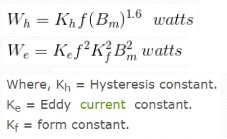
Hysteresis loss in transformer is denoted as,

How electrical transformers Work Video
Credit: 1
Discover more from Electrical Engineering 123
Subscribe to get the latest posts sent to your email.

It’s good to know that electrical distribution transformers are used to reduce voltages to usable levels. It sounds like there are a lot of different types of transformers to research if you want to get the right tool for the job. I think it’s important that you understand the limitations and capabilities of an array of different transformers so as to prevent any misunderstandings and accidents that may come from voltage overload.