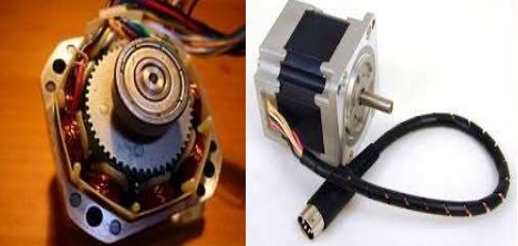
A stepper motor is an electromechanical device which converts electrical pulses into discrete mechanical movements. The shaft or spindle of a stepper motor rotates in discrete step increments when electrical command pulses are applied to it in the proper sequence.
Stepper motor (or step motor) is in fact a brushless DC electric motor that divides a full rotation into a number of equal steps. The name stepper is used because this motor rotates through a fixed angular step in response to each input current pulse received by its controller.
Stepper motor is popular due to the fact that it can be controlled directly by computers, microprocessors and programmable controllers(PLC).
The unique feature of a stepper motor is that its output shaft rotates in a series of discrete angular intervals or steps. Therefore stepper motors develop torques ranging from 1 µN-m (in a tiny wrist watch motor of 3 mm diameter) up to 40 N-m in a motor of 15 cm diameter suitable for machine tool applications.
The power output for stepper motor ranges from about 1 W to a maximum of 2500 W. The only moving part in a stepping motor is its rotor which has no windings, commutation or brushes. This feature makes the motor quite robust and reliable.
Working Principle of Stepper Motor
The motors rotation has several direct relationships to the applied input pulses. The sequence of the applied pulses is directly related to the direction of motor shafts rotation. The speed of the motor shafts rotation is directly related to the frequency of the input pulses and the length of rotation is directly related to the number of input pulses applied.
When a phase winding of a stepper motor is energized with current a magnetic flux is developed in the stator. The direction of this flux is determined by the “Right Hand Rule” The magnetic flux path developed when phase is energized with winding current in the direction.
The rotor then aligns itself so that the flux opposition is minimized. In this case the motor would rotate clockwise so that its south pole aligns with the north pole and its north pole is aligns with the south pole. To get motor rotate we can provide a sequence of energizing the stator winding in such a fashion that provides a rotating magnetizing flux field which the rotor follows due to magnetic attraction.

The torque produced by a stepper motor depends on several factors like step rate, the drive current in the winding and the drive design. The basic relationship which define the intensity of magnetic flux is defined by:
H = (N x i)/ l
where: H = Magnetic flux intensity
N = The number of winding turns
l = Magnetic flux path length
Stepper motor specifications
Steppers should be sized according to published torque curve, which is specified by the manufacturer at particular drive voltages or using their own drive circuitry. Step motors adapted to harsh environments are often referred to as IP65 rated. A stepper motor system consists of three basic elements:
- Indexers – The indexer (or controller) is a microprocessor capable of generating step pulses and direction signals for the driver.
- Drivers – The driver (or amplifier) converts the indexer command signals into the power necessary to energize the motor windings. .
- Stepper motors – The stepper motor is an electromagnetic device that converts digital pulses into mechanical shaft rotation.
Types of Stepper Motors
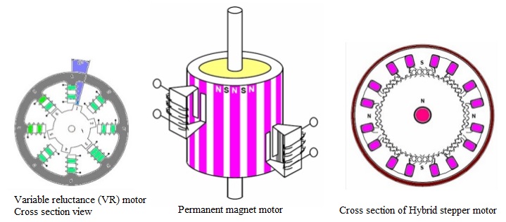
There are three basic type of stepper motor i.e. variable-reluctance motor, permanent magnet motor and hybrid motor.
- Permanent magnet motors use a permanent magnet (PM) in the rotor and operate on the attraction or repulsion between the rotor PM and the stator electromagnets.
- Variable reluctance (VR) motors have a plain iron rotor and operate based on the principle that minimum reluctance occurs with minimum gap, hence the rotor points are attracted toward the stator magnet poles.
- Hybrid stepper motor is named because it uses a combination of PM and VR techniques to achieve maximum power in a small package size.

In addition to being classified by their step angle stepper motor is also classified according to frame sizes which correspond to the diameter of the body of the motor. For instance a size 11 stepper motor has a body diameter of approximately 1.1 inches. Likewise a size 23 stepper motor has a body diameter of 2.3 inches (58 mm), etc.
The body length may however, vary from motor to motor within the same frame size classification. As a general rule the available torque output from a motor of a particular frame size will increase with increased body length.
Power levels for IC-driven stepper motors typically range from below a watt for very small motors up to 10 –20 watts for larger motors. The maximum power dissipation level or thermal limits of the motor are seldom clearly stated in the motor manufacturers data. To determine this we must apply the relationship PÊ=V ´ÊI.
Application of Stepper Motor
Stepper motor can be a good choice whenever controlled movement is required. It gives advantage in applications where you need to control rotation angle, speed, position and synchronism. Because of inherent advantages stepper motor have their place in many different applications.
Stepper motor is useful for operation control in computer peripherals, textile industry, IC fabrications and robotics etc. Other applications that require incremental motion include typewriters, line printers, tape drives, floppy disk drives, numerically-controlled machine tools, process control systems and X-Y plotters.
Computer-controlled stepper motor is one of the most versatile forms of positioning systems. They are typically digitally controlled as part of an open loop system, and are simpler and more rugged than closed loop servo systems.
Industrial applications are in high speed pick and place equipment and multi-axis machine CNC machines often directly driving lead screws or ball screws.
In the field of lasers and optics they are frequently used in precision positioning equipment such as linear actuators, linear stages, rotation stages, goniometers, and mirror mounts.
Other uses are in packaging machinery, and positioning of valve pilot stages for fluid control systems.
Advantages & Disadvantages of Stepper Motor
Excellent response to starting/stopping/ reversing.
It is possible to achieve very low speed synchronous rotation with a load that is directly coupled to the shaft.
The motors response to digital input pulses provides open-loop control, making the motor simpler and less costly to control. The motor has full torque at standstill (if the windings are energized)
Disadvantage of stepper motor is that if not properly controlled resonance can occur and stepper motor is not easy to operate at extremely high speeds hence causing vibrations.
Discover more from Electrical Engineering 123
Subscribe to get the latest posts sent to your email.

