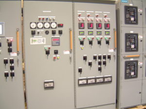
The apparatus used for switching , controlling & protecting the electrical circuits & equipment is known as switchgear. The switchgear equipment is essentially used with switching & interrupting currents either under normal or abnormal operating conditions.
A switchgear consists of devices such as switches , fuses , circuit breakers , relays etc. Basically every electric circuit needs a switching device & a protecting device. All equipment associated with the fault clearing process are converted by the term ‘switchgear’. Switchgear is an essential part of a power system & also that of an electric circuit.
Below are few features of LV/MV switchgears
Complete Isolation Reliability: The ability of the portion system to operate under the predetermined conditions is known as reliability. When fault occur on any power system , the switchgear must operate to isolate the faulty section from remaining circuit.
Discrimination: When fault occurs on any section of the power system the switchgear must be able to discriminate between the faulty section and the healthy section. It should isolate the faulty section from the system without affecting the healthy section.
Quick Response Operation: When fault occurs on any part of the power system, the switchgear must operate quickly so that no damage is done to generators, transformers, and other equipment by the short-circuit currents. If the fault is not cleared by the switchgear quickly, it is likely to spread into the healthy parts, thus endangering complete shut down of the power distribution system.
Components of Switchgear
Option of Manual Control: A switchgear must have provision for manual control. In case of electrical control fails , the necessary operation can be carried out through manual control.
Option for Instrumental Control: There must be provision for instruments which may be required. These may be in the form of ammeter or voltmeter on the unit itself or the necessary operation current & voltage transformers for connecting to the main switch board or a separate instrument panel.
Switchgear covers a wide range equipment with switching and interrupting currents under both normal & abnormal conditions. It includes switches, fuses, circuit breaker, relays.
Switches: A switch is a device which is used to open or close an electrical circuit in a convenient. The switches are classified are as follow:- Air-break switches oil switches
Fuses: A fuse is a short piece of wire or thin strip which melts when excessive current flows through sufficient time. whenever the current flowing through fuse element increases beyond its rated capacity then short circuit or overload occurs. This raises the temperature and the fuse element melts, disconnecting the circuit is protected by it.
Circuit Breakers: A circuit breaker is an equipment which can open or close under all condition i.e. no load, full load & fault condition. It is designed that it can be operated manually under normal condition & automatically under abnormal condition.
Relays: A relay is a device which detects the faults & supplies information to the circuit breaker for circuit interruption.
Installation Method of LV Switchgear / Panels
LV panels shall be inspected upon receipt at site for damages and compliance with the approved submittals and Single line Diagram. Upon completion of receiving inspection, the LV Switchgears shall be positioned at the respective substation locations with suitable crane arrangements.
LV switchgear panels found with transportation damages shall be recorded and notified to the concern party for further action. LV panels shall be covered with polythene sheets to protect from dust and moisture.
Ensure approved documents like shop drawing, single line diagram SLD, electrical room layout and load schedules are available with the installation team. Check the label/marking to ensure that it is the right panel and check the position according to the shop drawing.
Check the breaker rating and the provision for cable / bus bar termination. Set the breaker current rating as per approved shop drawing. Terminate the incoming and outgoing cable as per single line diagram using proper tools. Megger the panels after connecting the compartments. Megger the cables before terminating. Megger the panel after termination, when I/C open and O/G closed. Check working of motorized breakers.
Clean the termination and breaker cubicles with vacuum cleaner and hand brush to clean the dust and small metal pieces fallen during cable cutting and terminating process. Ensure the bus-bars and interconnecting terminals are free from dust and damage.
Provide identification for all the cable termination as per specification requirement and SLD. Dress the cables neatly with cable ties / cable cleat. Double check the connections by tightening the terminations.
Keep the approved single line diagram near the LV Switchgear (photo framed), wall mounted inside the substation. Inspection shall be offered for QC Verification before inspection from consultant and local authorities etc. Work Inspection Request shall be raised for Consultant’s inspection and sign off.
Discover more from Electrical Engineering 123
Subscribe to get the latest posts sent to your email.
