
This procedure defines the methods to be adopted for the installation of LV Switchgear panels on a project.
Document will ensure that the installation works at site are in compliance with the approved shop drawing, specifications, manufacturer manuals and approved material submittals.
Method statement also covers the procedure for material delivery inspection, storage in addition to the installation of LV switchgear.
Method statement covers the on-site inward installation and inspection to be applied to ensure that installation of LV Switchgear are supplied, installed and inspected.
Project Manager is overall responsible for the process of implementation of the works.
The Construction Manager/Site Engineer will be responsible for all construction activities at the site and will directly supervise through erection supervisor/skilled workmen at the work site.
QA/QC Engineer will be responsible for arranging and controlling the inspection and testing activities.
This is to ensure that all works are in accordance with the project specifications.
The work methods are summarized as follows:
- Preparation of the Works
- Delivery and inspection of LV switchgear materials upon delivery at site
- Setting out of works
- Installation of LV Switchgear
- Inspection of LV Switchgear
List of Equipment’s
- Electric drill hammer
- Torque wrench
- Electricians tool box
- Certified mobile scaffolds / Step ladder
- Multi tester/ Megger tester
- Lifting Equipment/Chain block
- PPE for all staff and labor
Preparation for the LV Panels Installation
All system equipment shall be carefully off-loaded at site using the necessary manpower, appropriate shifting machinery and equipment to ensure that no damage is caused to the material.
All received material will be checked for conformance of material approval and confirmation will be given by store keeper or site engineer before offering inspection. All material shall be stored in a clean, dry place and adequate cover shall be provided to avoid damages.
Materials found not to be as per requirement or with damage or defect will be set aside. These will be properly labeled and returned to the supplier. These will also be reported in a Non-Conformance Report to the QA/QC Engineer.
QA/QC Mechanical Inspector shall inspect the materials on receipt of a Request for Inspection from construction.
Materials shall be inspected to ensure that the materials are as per approved Material submittals in terms of their make, model type, country of origin and capacity. Any discrepancies, damage etc., found will be notified and reported for further action. Material shall be submitted for Material Inspection (MIR) to Consultant for final approval & acceptance before proceeding with installation.
Verification, inspection checklist, and test will be verified recorded on approved forms and sign by QA/QC Engineer, main contractor representative and consultant.
All relevant Documentation (drawings, material submittals, method statements etc.) and material applicable for particular area of work will be checked by site supervisor/engineer prior commencement of work.
The supervisor and foreman will examine surfaces to receive the LV Panel for compliance with installation tolerances and other required conditions, as described in the installation requirement. Installation will not proceed until unsatisfactory conditions have been corrected.
The supervisor and foreman will orient and familiarize all the technicians and labors involved in the installations regarding the relevant approved shop drawings, technical submittals, installation procedures and details, acceptance criteria and safety requirements.
All installation / construction / testing works shall be carried out in compliance with the contract specifications and project safety manual.
Installation of LV Panel
No work will commence in any LV room until all the necessary builders work has been completed and all doors, windows, locks etc., are in place for security of installed equipment.
The LV room will be inspected prior to commencement of the installation to ensure that the building and cable trenches are acceptable. This inspection will consist of but not limited to the following:
All unnecessary building material such as timber framework, scaffolding, debris etc., has been cleared off.
The foundations have been installed to suit the particular equipment i.e. correct dimensions etc.
The door openings are to the required dimensions.
For LV panels, floor levels are within + 1.5 mm between two adjacent cubicles and not more than 3mm between one end of the board to the other.
A minimum clearance of 750mm is available around the switchboard and a clearance of not less than 1500mm is provided in the front of the switchboard.
Space in front of the switch panel must be flat and level to ensure that the carriage can be withdrawn and inserted easily and it is standing in a vertical position at the point of entry into the housing.
Panel board shall be provided with a 1m wide carbon free rubber mat or mats, having a cross ribbed upper surface and being of such continuous length to suit the full operating extent of each switchboard and heavy grade bitumastic felt shall be provided between the floor and the switchboard.
The switchboard will be checked for any damage prior to transportation from the stores compound to the particular LV room where it is to be installed. When unpacking the switchboard panels from the crates, care will be taken to avoid scratching or denting finished surfaces.
On satisfactory completion of the above, the LV panel will be loaded onto or flatbed truck using the lifting eyes provided by the Manufacturer and positioned on wooden battens then securely tied down to avoid any movement of the load during transportation to the LV room and the insertion of pipe rollers under the base of the switchboard.
Each section will then be maneuvered onto its final position and the rollers removed accordingly.
On arrival at the LV room, the LV panel will be off-loaded from the truck into the LV room.
Each section of the LV panel will be lifted by a chain block to facilitate the removal of the wooden battens and the insertion of pipe rollers under the base of the LV panel. Each section will then be maneuvered onto its final position and the rollers removed accordingly. When moving the equipment by pipe rollers floor protection using plywood panels with thick tarpaulin material will be laid on the floor to avoid any damage to the floor finish.
Good care will be taken in all these operations, to avoid scratching or denting of finished surfaces of the switchboard.
LV panel sections will be lined up using shims if necessary and fitted with coupling bolts. For LV panels, switching station floor level will be checked to make sure it is within 1 mm over a 1meter length section.
Fixing holes will be pre-drilled with the template provided by the supplier and prepared in positions shown on the layout drawings within a tolerance of ± 1.5 mm.
After aligning all sections of the LV panel, foundation bolts will be inserted and well secured.
A manufacturer representative will do the busbar joints in LV panel. Only high tensile grade steel bolts supplied by the Manufacturer will be used for busbar joints and they will be torque to manufacturer’s specification torque.
Earth bar joints will be lubricated and connected. Connection steel bolts will be tightened to manufacturer’s specification torque.
Any bus wiring or interconnecting cables which has been disconnected for shipping will now be connected back.
After installations are complete, where shop applied paint coating is abraded, all bare steel including bolts and nuts shall be thoroughly cleaned and each item will be painted with the same paint as used for shop coating.
Earth wire / connections to hinged panel doors will be checked and tightened where necessary.
All lifting equipment and supports will be checked to ensure satisfactory operation and condition before work commences. During installation work Safety Officer will be present to make sure maximum safety precautions are adhered to throughout the operation.
Access to busbars and busbar connections shall be possible only after the removal of covers secured by bolts or studs.
Such covers shall be identified by externally engraved flexible type ‘Traffloyte’ laminate labels bearing the inscription ‘BUSBARS’ in red lettering not less than 10mm high, on a white background.
Warning labels shall be of Traffolyte engraved laminate with red lettering on a white background, and shall bear the inscription ‘DANGER – LIVE PARTS OVER 230V’ in both English and Arabic languages in letters not less than 10mm high.
After the erection, the LV panel will be protected by a cartoon cover to avoid entry of dirt and dust and remove until the termination of cables starts.
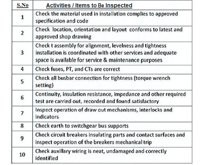
Inspection and Testing Procedure
Ensure that all instruments and devices intended to use for testing must be calibrated. Attached all calibration certificates in the work inspection request showing the date and record of calibration.
Test insulation resistance of switchgear bus with a 1-minute test (phase to phase and phase to ground).
A high voltage pressure test shall be carried out with all isolators dosed and power fuses fitted but having all control circuits disconnected. The panels shall withstand for one minute a pressure of 2kV across the following points.
a) Phase to phase
b) Phase to neutral
c) Phase to earth
d) Neutral to earth
Repeat Test insulation resistance of switchgear bus with a 1-minute test (phase to phase and phase to ground).
Test Insulation resistance of each circuit breaker (closed position) with a 1-minute test (phase to phase and phase to ground).
Test circuit breaker contact resistance with a micro-ohmmeter.
Test insulation resistance of all instrument transformers with a 1-minute test.
Calibrate and test each circuit breaker protective device with settings according to drawings and specifications.
With CT disconnected, test CT secondary circuit for continuity and operation of applicable relays and meters by applying current to the CT secondary winding.
Test PT secondary circuit by applying voltage to the PT secondary, with PT disconnected, verifying operation of all applicable relays and meters.
Test window-type ground CTs and their circuits by applying current to a conductor passed through the window.
Test operation of all space heaters including switching and indicating devices.
Sharing is caring:

Discover more from Electrical Engineering 123
Subscribe to get the latest posts sent to your email.