In this method of inter-connection the similar ends either the ‘start’ or ‘finish’ are joined together at point N. This common point N is called star point or neutral point. Ordinarily only three wires are carried to the external circuit giving 3-phase, 3-wire star connected system but sometimes a fourth-wire, known as neutral wire is carried to the neutral point of the external load circuit giving 3-phase, 4 wire star connected systems.
The voltage between any line and the neutral point (i.e. voltage across the phase winding is called the ‘phasevoltage’ (Eph); while the voltage available between any pair of terminals (or outers) is called the ‘line voltage’ (EL).
In star connection, there are two-phase windings between each pair of terminals, but since their similar ends have been joined together, they are in opposition.Obviously, the instantaneous value of potential difference between any two terminals is the arithmetic difference of the two-phase e.m.fs. concerned. However, the r.m.s. value of this potential difference is given by the vector difference of the two-phase e.m.fs.
Below figure also shows the vector diagram for phase voltages and currents in a star connection where a balanced system has been assumed.
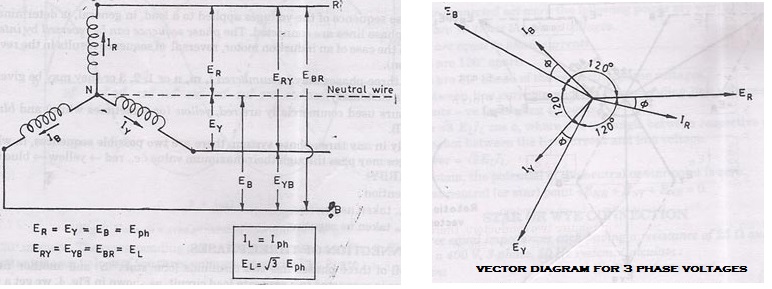
A balanced system is one in which:
(i)the voltages in all phases are equal in magnitude and differ in phase from one another by equal angles, in this case, the angle = 360/3 = 120°,
(ii).the currents in the three phases are equal in magnitude and also differ in phase from one another by equal angles. A three-phase balanced load is that in which the loads connected across the three-phases are identical]. Thus, we have:
ER= EY= EB= Eph(phase e.m.f.)
Line voltage,
ERY(=EL) = Vector difference of ERand EY
=ER-EY
Line voltage,
EYB= EY– EB
Line voltage,
EBR =EB-ER.
Relation Between Line Voltages and Phase Voltages
The potential difference between outers R any Y is
ERY= ER–EY [vector difference]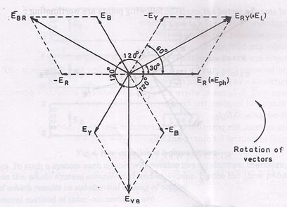
or
ERY= ER+ (-EY) [vector sum]
Hence, ERYis found by compounding ER and EY reversed and its value is given by the diagonal of the parallelogram. Obviously the angle between ER and EY reversed is 60oand the value
ERY (or EL) = …(1)
Similarly
EYB(= EL) = EY– EB=
and EBR(=EL) =EB-ER =
i.e., ERY= EYB= EBR= EL=
Hence, (i.e., Line voltage = phase voltage).
Relation between Line Currents and Phase Currents
Since in star-connected system each line conductor is connected to separate phase, so the current flowing through the line and phase are same.
Current in outer (or line) R = IR
Current in outer Y = IY
Current in outer B = IB
Since IR= IY= IB= say, Iph-the phase current
Line current, IL= Iph
Power
If the phase current has a phase difference of with phase voltage,
Power per phase = Ephlph cos
Total power (true), P = 3 power per phase
P = 3 EphIph cos
Hence in terms of line values, the above expression becomes
Eph= and Iph= IL.
In a balanced star-connected net work the following points are worth noting :
- Line voltages are times the phase voltages.
- Line currents are equal to phase currents.
- Line voltages are 120O apart.
- Line voltages are 30O ahead of the respective phase voltages.
- The angle between line currents and the corresponding line voltages is (30O ± ) + for
lagging currents – ve for leading currents. - True power = cos , where is the angle between respective phase current and phase voltage, not between the line current and line voltage.
- Apparent power = –
- In balance system, the potential of the neutral or star point is zero.
Potential at neutral (or star) point =ENR+ ENY + ENB = O.
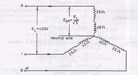
Example 1.Three equal impedances each having a resistance of 25 Ω and reactance of 40 Ω
are connected in star to a 400 V, 3-phase, 50 Hz system. Calculate:
(i) The line current
(ii) Power factor, and
(iii) Power consumed.
Solution. Resistance per phase, Rph= 25 Ω
Reactance per phase, Xph= 40 Ω
Line voltage, EL= 400 V
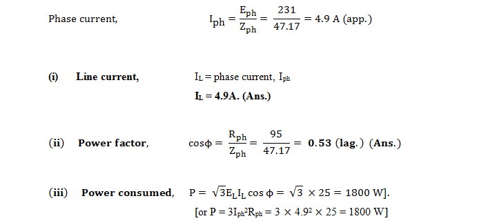
Line current, IL.:
Power factor, cos
Power consumed, P

Example 2.Three identical coils are connected in star to a 400 V (line voltage), 3-phase A.C.
supply and each coil takes 300 W. If the power factor is 0.8 (lagging). Calculate:
(i) The line current,
(ii) Impedance, and
(iii) Resistance and inductance of each coil.
Solution. Line voltage, EL = 400 V
Power taken by each coil, Pph= 300 W
Power factor, cos = 0.8 (lagging)
IL ; Z ; Zph ; Lph :

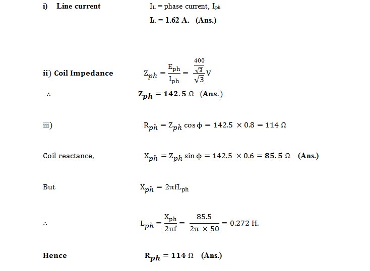
and Lph = 0.272 H Answer.
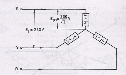
Example 3.In a 3-phase, 3-wire system with star-connected load the impedance of each phase is (3 + j4) Ω. If the line voltage is 230 V, calculate:
(i) The line current, and
(ii) The power absorbed by each phase.
Solution. Line voltage, EL = 230 V
Resistance per phase, Rph = 3 Ω
Reactance per phase, Xph = 4 Q
IL; Pph:

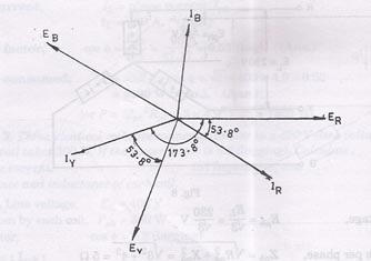
Solution by symbolic Notation. In below figure ER, EY and EB are the phase voltages whereas IR, IY and IB are phase currents.
Taking ER as the reference vector, we get
This current lags behind the reference voltage (ER) by 8’
It lags the reference i.e., ER by 8’ which amounts to lagging behind its phase voltage EYby 8’.
This current leads ER by which is the same as lagging behind its phase voltage by .
Let us consider R-phase for calculation of power
ER = (133 + j0) ; IR = 26.6 (0.6 – j0.8) = (15.96 – j21.28)
Using method of conjugates, we get
PVA = (133 – jO) (15.96 – j21.28) = 2116 – j2830
Real power absorbed/phase = 2116 W
Example 4.A star-connected, 6000 V, 3-phase alternator is supplying 4000 kW at factor of 0.8. Calculate the active and reactive components of the current in each phase.
Solution. Line voltage, EL = 6000 V
Power supplied, P = 4000 kW
Power factor, cos = 0.8
Active and reactive components of current:
We know that, P = ELIL cos
4000 x 1000 = 6000 IL. 0.8
Active component = Iph cos = 481 0.8 = 384.8 A. (Ans.)
Reactive component = Iph sin = 481 0.6 = 288.6 A. (Ans.)
Example 5. In a 3-phase, 4-wire system, two phases have currents of 20 A and 12 Air.
power factors of 0.8 and 0.6 respectively, while the third phase is open-circuited. Calculate the
in the neutral and draw the vector diagram.
Solution. Refer Figs. below.
cos 1 = 0.8
1 = cos-1 0.8 = 36° 52′ (lag)
cos 2 = 0.6
2 = cos-1 0.6 = 53° 8′ (lag)
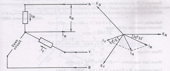
Let ER be the reference vector.
Then IR = 20 –36° 52′ = 20 (0.8 –j0.6) = (16 – j12)
and IY = 12 –173° 8′ = 12 (-1 –j0.12) = (-12 – j1.44)
The current through the neutral
IN=IR+lY
= (16 – j12) + (-12 –j1.44) = 4 –j13.44 = 14 –73° 24′
Hence, current in the neutral = 14 – 73° 24′. (Ans.)
Example 6. A balanced 3-phase star connected load of 100 kW takes a leading current of
80 A, when connected across a 3-phase, 1100 V, 50 Hz supply. Find the circuit constants of the load
per phase.
Solution. Given: P = 100 kW; Iph(= IL) = 80 A; EL = 1100 V; f= 50 Hz
Circuit constants of the load per phase, R, C :
As the 3- load is balanced and star connected, line or phase current,
Example 7. Three identical star-connected coils take 8 k W at a power factor 0.8 when connected
across a 460 V, 3-phase, 3-wire supply. Find the circuit constants of the load per phase.
Find the line currents if the coil in phase C is short circuited. Supply phase sequence isA-B-C.
Solution. Given: P = 8 kW ; V = 460 volts; cos θ = 0.8
Circuit constants of the load:
Load resistance, R = Z cos θ = 21.16 × 0.8 = 16.93 Ω. (Ans.)
Load reactance, X = Z sin θ = 21.16 × 0.6 = 12.7 Ω. (Ans.)
Line currents if the coil in phase C is short circuited:
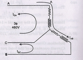
The connection arrangement is shown in figure above when coil C is shorted.
Given that phase sequence is A-B-C.
Hence, EAB = 460 0°
EBC = 460 -120°
ECA = 460 +120°
Also, Z = 21.6 36.8°
Line current in line A = IAB -ICA
= 10.87 36.8° – 21.74 83.2°
= 10.87(0.8 – j0.6) – 21.74(0.118 + j0.993)
= 8.70 – j6.52 – 2.56 – j21.59 = (6.14 – j28.11)A. (Ans.)
Line current in line B = IBC -IAB
= 21.74 -156.8° -10.87 – 36.8°
= 21.74(- 0.92 – j0.394) – (8.70 – j6.52)
= – 20.0 – j8.56 – 8.70 + j6.52 = (- 28.70 – j2.04)A. (Ans.)
Line current in line C = ICA – IBC
= (- 2.56 – j21.59) – (- 20 – j8.56) = – 2.56 – j21.59 + 20 +8.56
= (17.44 – j13.03)A. (Ans.)
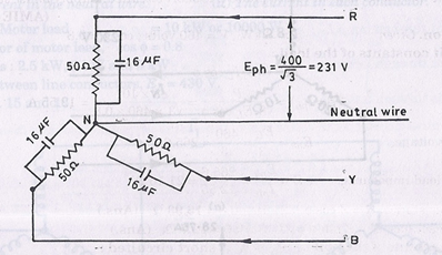
Example 8. In a star-connected load each phase consists of a resistance” of 50 Ω in parallel with a capacitor of capacitance 16 µF. When it is connected to 400 V, 3-phase, 5 Hz supply, calculate:
(i) The line current
(ii) The power factor,
(iii) The power absorbed, and
(iv) The total kVA
Solution. Resistance per phase, R = 50 Ω
Capacitance, C = 16 µF = 16 × 10-6 F
The circuit is shown in below figure:
Admittance of each phase,
lph = Eph.Yph = 231 (0.02 + j0.005) = 4.62 + j1.155 = 4.76 14°
| .. h=4.76A.. h =4.76AHence, line current = 4.76 A.
(ii) Power factor |
| (Ans.) |
For a star connection, Iph = IL
IL = 4.76 A
Hence, line current = 4.76 A. (Ans.)
(ii) Power factor = cos 14° = 0.97 (leading). (Ans.)
(iii) Now Eph = (231 + j0); lph = (4.62 + j1.155)
PYA = (231+ j0) (4.62 – j1.155)
= 231 × 4.62 – j1.155 × 231 = 1067.22 – j266.8
= 1100 14° (per phase)
Total power absorbed = 3 × 1067.22 = 3201.66 W = 3.201 kW. (Ans.)
(iv) Total volt-amperes = 3 × 1100 = 3300 VA = 3.3 kVA. (Ans.)
Example 9. A 3-phase, star-connected system with 230 V between each phase and neutral has resistance of 8, 10 and 20 Ω respectively in three phases, calculate:
(i) The current flowing in each phase, (ii) The neutral current, and
(iii) The total power absorbed.
Solution. Refer Figs. below.

Phase voltage, Eph = 230 V
ii) The above currents are mutually displaced by 120°. The neutral current IN is the vector sum of these three currents.
IN can be found by splitting up these three-phase currents into their X-components and Y-components and then by combining them together.
ƩX-components = 23 cos 30° – 11.5 cos 30° =11.5 cos 30° = 9.96 A
ƩY-components = 28.75 – 23 sin 30° -11.5 sin 30° = 28.75 – 34.5 sin 30° = 11.5 A
Neutral current, IN = = 15.21 A. (Ans.)
(iii) Total power absorbed,
Example 10. In a 3-phase, 4-wire system, there is a balanced 3-phase motor load taking 10 kW
at a power factor of 0.8 lagging while lamps connected between phase conductors and the neutral are
taking 2.5 kW, 2 kW and 5 kW respectively. Voltage between line conductors is 430 V. Calculate:
(i) The current in the neutral wire. (ii) The current in each conductor.
Solution. Motor load = 10 kW or 10000 W
Power factor of motor load, cos θ = 0.8
Lamp loads: 2.5 kW, 2 kW and 5 kW
Voltage between line conductors, EL = 430 V.
Refer Figs. 15, and 16.
Let us first find the current in the neutral wire due to lamp loads L1 (2.5 kW), L2 (2 kW) and
L3 (5 kW) respectively.

The neutral current is the vector sum of three lamp currents. Resolving them into their X and Y components, we have
X = 8.06 cos 30° – 20.16 cos 30° = -10.48 A
Y = 10.08 – 8.06 sin 30° – 20.16 sin 30° = – 4.03 A
Line current drawn by the balanced 3-phase
Each conductor carries-two currents:
(i) a current of 16.78 A at’O.8 power factor lagging; and
(ii) appropriate lamp current which is in phase with the voltage.
Actual component of load current = 16.78 × 0.8 = 13.42 A
Reactive component = 16.78 × 0.6 = 10.07 A
Discover more from Electrical Engineering 123
Subscribe to get the latest posts sent to your email.

