Below is the list of some important transformer tests which are conducted on site before final testing and commissioning is planned.
Insulation resistance test
In this test the insulation resistance is measured by applying appropriate voltage across the terminals as mentioned below:
- HV to Earth+LV and ground is measured with 5kV test voltage
- LV to Earth+HV and ground is measured by applying 1kV test voltage
- HV to LV is measured by applying 5kV test voltage
Winding resistance test
Using a winding resistance meter the HV and LV winding resistance are measured and recorded, the ambient temperature at the time of test is noted for temperature corrections. The test is repeated for all taps on HV winding.
Transformer turns ratio
Test and vector group is verified using Megger TTR
Magnetic Core Balance test
For magnetic balance test apply the two phase voltage between the 1U & 1V and the tap position is kept at service tap. Then measured voltage on HV & LV in all combinations as tabulated in the test format and lock that applied voltage between 1U & 1W, 1W&1V and measured the voltage
Magnetizing Current
The magnetizing current drawn by the transformer at the LT mains supply Current measured for the HV winding for all phases at all the taps keeping the LV terminals open circuited
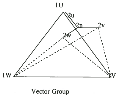
Vector group test
For Dyn11 vector group, Keep the terminals 1U (HV R phase) & 2U (LV R phase) shorted, a 3 phase, 415V, supply is applied on the HV side of the transformer, the tap position is kept at service tap. The voltages on HV & LV are measured in all combinations as tabulated in the test format and it is verified that the voltage 1V-2V is equal to 1V-2W and 1W-2V is greater than 1W-2W. This could be seen in the vector diagram.

Protective device operation
The transformer protective devices are operated/simulated as described in the project specifications.
Discover more from Electrical Engineering 123
Subscribe to get the latest posts sent to your email.

