
This electrical method statement covers the installation, testing and commissioning procedure for the master antenna or MATV Distribution system. All the materials will be as approval from the consultant engineer and installation & routing will be as per the shop drawings approvals for MATV system.
Minimum tools and equipment’s for the installation and testing of system works are as follows:
- Screw driver set
- Cutting Pliers
- Soldering Iron
- Label Printer
- Insulation tape
- Frequency meter
- Multi meter
- Portable TV
- Electrician’s tools
Adhere to drawings as closely as possible. The right is reserved to vary the runs and sizes of conduits & cable trays and to make offsets but maintain as far as possible the free area of each section, where necessary to accommodate conditions arising at the building.
The installation will be carried out according to the approved shop drawings, site requirement and the Engineer’s instruction at site and comply with requirements of local authorities.
Installation of Cables and Tap–off units
Install all cables inside the conduit and/or cable tray of suitable sizes
Make sure that all cable junctions and taps are easily accessible for maintenance and inspection purposes.
Install and fasten the cables without causing sharp bends or rubbing of the cables against sharp edges and must be fastened with hardware which will not damage or distort them.
Provide tap-off units as per approved shop drawings.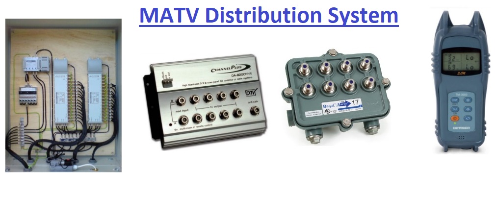
RG 6 Coaxial cables shall be provided between TV outlet and Tap-off units.
RG 11 Coaxial cables shall be provided between Tap-off units and Distribution Amplifiers.
Cables and Tap off unit shall be labelled at the equipment terminals.
Power provision
Power for all Fiber Optic Receivers shall be provided on a dedicated circuit, being connected to the UPS unit in the control room.
Installation of TV+SAT-IF OPTICAL RECEIVER (FRD-350)
FRD-250 is suitable for indoor application only. Use two Q4.2×32 screws to fix the housing to the wall through the two holders at the top and bottom.
The optical connection is made using a single mode fibre optic cable of 3mm with SC/APC8 connector:
Remove the protective cover from the optical head of the receiver, as well as protection cap from the connector on the single fiber cable.
Plug the connector into the head, making sure that the ledge on the connector meets the slot on the head. Press home.
Installation of CATV EXTENDER AMPLIFIERS
Use four Ф4.2 x32 screws for the wall-fixing through the holders of the housing.
Connect the input and output RF coaxial lines to the amplifier.
Installation of VHF/UHF TV MODULATOR
Remove cover.
Screw the modulator to the wall.
Put the plastic cover on.
Installation of Equipment Rack in Equipment Room
All EQM, CGT, EAM, MAO and Fiber optic Transmitter are installed in a metal rack complete with glass doors with hinged doors and locks so as to be accessible for maintenance without interference to other nearby equipment.
The location of the rack will provide for adequate installation space for correct mounting of components and associated hardware, and will observe clearances for connecting cables and installation tools.
MATV Pre Commissioning Checks
Verify that units and controls are properly installed, connected, and labelled and that interconnecting wires and terminals are identified.
Pre-setting: align and adjust system and pre-test components, wiring, and functions to verify that they comply with specified requirements. Replace malfunctioning or damaged items. Retest until satisfactory performance and conditions are achieved.
Test Schedule: schedule tests after presenting has successfully been completed and system has been in normal functional operation for at least 14 days. Provide a minimum of 10 days’ notice of test schedule.
MATV Operational Tests
Perform operational system tests to verify that system complies with project specifications. Include all modes of system operation. Test equipment for proper operation in all functional modes.
MATV Distribution System Acceptance Tests include the following:
Instrumentation
Use a field-strength meter rated for minus 40-dB mV measuring sensitivity and a frequency range of 5 to 862 MHz, minimum. Provide documentation of recent calibration against recognized standards.
Signal Level: use a field-strength meter to measure signal levels at TV system outlets via a QAM set-top-box. Readings on each of the channels designated to be received must be within specified limits.
Signal-to-Noise-Ratio Test: use a field-strength meter to make a sequence of measurements at the output of the last distribution amplifier or of another agreed-upon location in system. With system operating at normal levels, tune meter to the picture carrier frequency of each of the designated channels in turn and record the level. With signal removed and input to corresponding head-end amplifier terminated at 75 ohms, measure the level of noise at the same tuning settings. With meter correction factor added to last readings, differences from first set must not be less than 45 dB.
Picture-Quality Test: connect a standard TV receiver to each a STB system outlet and observe picture quality on designated channels. No evidence of cross-channel inter-modulation, ghost images, or beat interference should appear.
Qualitative and Quantitative Performance Tests: demonstrate reception quality of color television program transmissions at each system outlet from each designated channel and source. Quality shall be equal to or superior than that obtained with performance checks specified below, using a standard, commercial, cable-ready, color-television receiver.
-
- Carrier Level Stability, Short Term: level does not change more than 5 dB.
- Digital Carrier Response: signal amplitude is plus or minus 3 dB, maximum.
- Channel Frequency Response: across any 8-MHz channel signal amplitude is plus or minus 3 dB, maximum, unless otherwise indicated.
- Carrier-to-Noise Ratio: 45 dB or more, unless otherwise indicated.
- Terminal Isolation TV to TV: 25 dB, minimum.
- Terminal Isolation between TV and FM: 35 dB, minimum.
- Hum Modulation: 2 percent, maximum.
- RF FM Carrier Level: 13 to 17 dB below video carrier level.
- FM Frequency Response: more than the 88- to 108-MHz frequency range, signal amplitude is plus or minus 0.75 dB, maximum.
Equalizing Video Signals: where system performance may be degraded in certain operating modes revise component connections and install video distribution amplifiers and attenuators as required providing a balanced signal across the system.
Record test results.
Retest: correct deficiencies identified by tests and observations and retest until specified requirements are met.
Documentation
As Built Drawings for MATV System
Operation & Maintenance Manual
Testing and Commissioning Report.
Handing Over Training
Training shall be provided to the client representatives on the MATV system operation and troubleshooting.
Sharing is caring:

Discover more from Electrical Engineering 123
Subscribe to get the latest posts sent to your email.